Reliable heavy-duty gearing depends on more than a catalogue torque rating: duty cycles, tooth stresses, heat, alignment, lubrication and manufacturing quality all interact. By the end, you will be able to convert machine conditions into a gear specification, identify the evidence that supports a supplier’s rating, and spot designs that are unsuitable for continuous service.
Key takeaways
- Calculate torque at every speed and load point, not only from nameplate torque.
- Choose gear arrangements by heat dissipation, load direction and available machine space.
- Specify tooth material, hardening treatment and geometry for the actual load spectrum.
- Demand test records, inspection data and operating limits before approving the gearbox.
Start with the real duty cycle, not the nameplate torque
Calculate survival from the machine’s load spectrum, not the nameplate torque. Convert transmitted power and speed into output torque with T = 9,550P/n in newton-metres, then verify the gearbox ratio, output torque and speed at every operating point.
Record peak torque separately; a motor’s starting torque, jam or rapid reversal can exceed its steady value several times.
Build the duty case from these inputs:
- Continuous duty: count operating hours at each load and speed, including the longest uninterrupted run.
- Intermittent duty: record run time, rest time, starts per hour and the total duty cycle.
- Shock loads and reversals: identify crushers, conveyors, mixers, hoists and machines that stop, impact or reverse under load.
- Service factor: apply the factor for the driven machine, prime mover, starts, shocks and required life rather than accepting a generic catalogue value.
Use the resulting load spectrum to calculate tooth-root bending and flank contact stress. ISO 6336 and AGMA methods include geometry, size, dynamic, material and reliability factors, but a passing rating does not cover a jam torque, housing deflection, misalignment or lubricant failure.
Check thermal capacity too: mesh sliding, bearings and oil churning turn transmitted power into heat. The gearbox fails its continuous duty if steady oil or housing temperature exceeds the lubricant, seal or material limit, even when tooth stress remains below the calculated rating.
Match the gear arrangement to heat, load and machine layout
Choose the gear mesh and gearbox layout together: a continuously operating machine needs enough thermal capacity for steady heat generation, not merely a tooth rating at the nameplate torque.
| Gear arrangement | Main advantage | Best fit |
|---|---|---|
| spur gears | Simple, efficient, low cost | Low-speed inline drives where noise and shock are controlled |
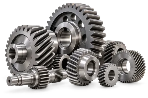
| helical gears | Higher contact ratio, smoother and quieter running | Continuous high-load service; account for axial load and bearing capacity |
| bevel gears | Changes the drive direction | Right-angle gearbox layouts where output-shaft direction matters |
| worm gears | Large reduction in one stage and self-locking potential | Low-speed positioning; reject them when efficiency and heat generation dominate |
| planetary gears | High torque density and broad ratio range | Compact continuous drives, provided load sharing is engineered |
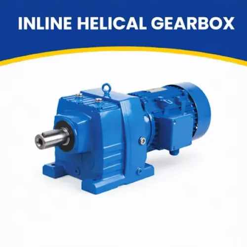
| inline gearbox | Straight-through shaft path | Machines with aligned input and output shafts and accessible mounting |
| parallel-shaft gearbox | Compact offset shafts | Conveyors and mixers with limited radial space |
| right-angle gearbox | Turns power through 90 degrees | Layouts that demand a transverse output shaft |
Do not specify minimum backlash by habit. The clearance must accommodate lubricant film, thermal expansion, manufacturing tolerance and shaft-position changes; too little causes interference or seizure as temperature rises, while too much increases impact, noise and position error. Check shaft alignment, mounting orientation and housing stiffness before selecting the unit.
For planetary gears, request floating members or another documented load-sharing design; otherwise one planet can carry far more than its nominal share. Confirm the calculated thermal capacity at the actual speed, ratio and duty cycle.
Specify the tooth material, treatment and geometry that carry the load
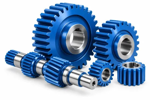
Specify carburized steel when you need a hard, wear-resistant flank with a tough tooth root. Target 58–62 HRC case hardness, then verify effective case depth against tooth size, bending stress and core hardness. A shallow case accelerates pitting and root damage; excessive depth can increase distortion and reduce core toughness.
Nitrided steel suits moderate-to-high contact stress where low distortion matters, while through-hardened steel fits smaller, lower-shock gears when uniform hardness and adequate core toughness are acceptable.
| Material and process | Load-life advantage | Checks to require |
|---|---|---|
| Carburized steel | Hard case plus tough core for high contact and bending fatigue | Effective case depth, core hardness, distortion and hardness profile |
| Nitrided steel | Hard nitrided layer with minimal dimensional change | Compound-layer control, case depth, flank finish and brittleness |
| Through-hardened steel | Uniform hardness for smaller or moderate-load gears | Full-section hardness, impact toughness and crack inspection |
Choose accuracy by speed, load and noise target: state an ISO 1328 accuracy class and corresponding AGMA quality grade rather than writing “precision.” Hobbed gears and shaped gears suit many duties; shaved gears improve flank finish, while ground gears provide tighter geometry and lower transmission error.
After grinding, require grinding burn checks using nital etching, hardness checks and magnetic-particle inspection where appropriate.
Specify tip relief for tip interference and impact control, plus lead crowning to tolerate alignment error and deflection. Excessive correction reduces contact area and load capacity, so validate both against the operating torque range.
Control the supporting system: bearings, lubrication, alignment and temperature
Strong gear teeth fail when supporting parts shift load onto a small area or destroy the oil film. Shaft stiffness sets how far the shaft bends, while bearing clearance and preload set shaft position.
Poor bearing life, coupling misalignment and housing deflection can change center distance under load, creating flank overload or root bending that tooth-strength calculations miss.
A loaded contact pattern is more revealing than backlash alone. Check tooth marking at operating load and inspect for edge contact: a pattern crowded at one end concentrates stress and accelerates micropitting, macropitting or tooth breakage. Set backlash within its specified range, but do not treat a correct unloaded reading as proof of alignment.
Control the failure paths with a defined operating and maintenance plan:
- Specify oil cleanliness using ISO 4406, with filtration sized for the gearbox, bearings and load. Hard particles damage raceways and gear flanks; water contamination weakens the lubricant film, promotes corrosion and depletes additives.
- Select lubricant viscosity that maintains film thickness at actual speed and load. Low viscosity or inadequate oil delivery raises scuffing risk during starts, speed changes and high sliding.
- Measure cooling performance and steady-state temperature at the housing and oil. If temperature exceeds the lubricant or seal limit, viscosity falls; improve cooling or reduce load before fatigue damage follows.
Turn the specification into supplier evidence and an operating check
A catalogue torque rating is not approval evidence. Require records that connect the proposed gearbox to your peak torque, jam condition, speed range, starts, reversals and heat rejection.
1. Request the inspection report, material certificate, hardness and case-depth report for gears, shafts and planet pins. Check specified values against the drawing, heat-treatment requirement and acceptance limits.
2. For a load-sharing planetary gearbox, request measured planet-load distribution or a calculation showing carrier, sun, ring and pin deflection. Nominal torque divided by the number of planets is not proof of equal sharing.
3. Demand a contact-pattern test under representative load. The report should show flank marking, tooth alignment and whether tip relief or lead crowning prevents edge loading.
4. Require a thermal test at rated speed and continuous load, recording oil and housing temperature until steady state. Reject a design that exceeds the lubricant, seal or material limit, even when tooth stress passes calculation.
5. Include a factory acceptance test with torque, speed, noise, leakage and temperature results. For variable-speed drives, require a torsional resonance check and confirmation that operating speeds avoid the resonance range and damaging gear-mesh frequency.
6. Set a baseline before installation: vibration spectrum, acoustic emission, oil-debris analysis and temperature trend. Repeat condition monitoring at defined intervals; a rising overall vibration value alone cannot identify tooth damage.
OPTIGEAR can use these records to distinguish a gearbox built to the specification from one supported only by a catalogue claim. Keep every result with serial number, test load, lubricant and instrument calibration details.
Related products
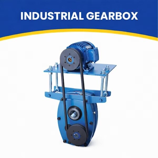
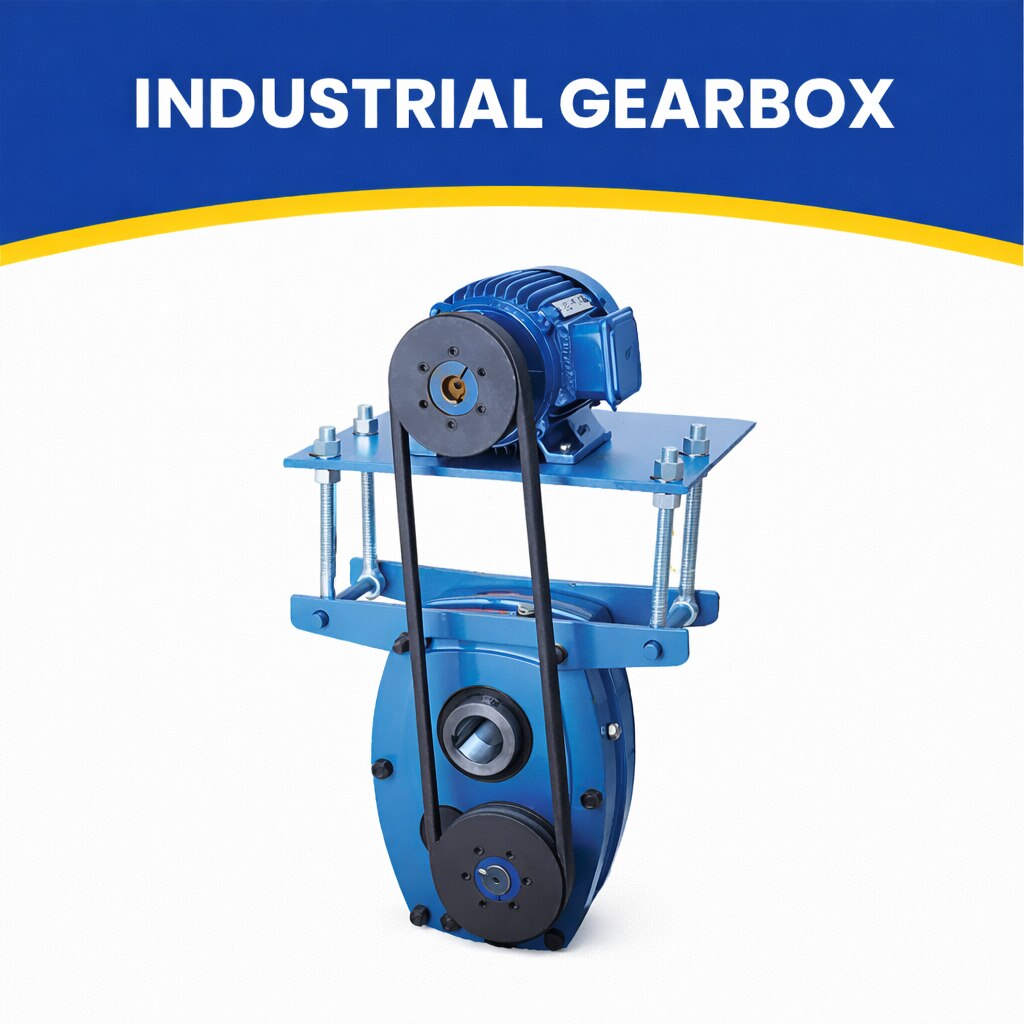 | By JRB Engineering Works JRB Engineering Works is a trusted manufacturer and supplier of high-performance Industrial Gearboxes, engineered to deliver... View product → |
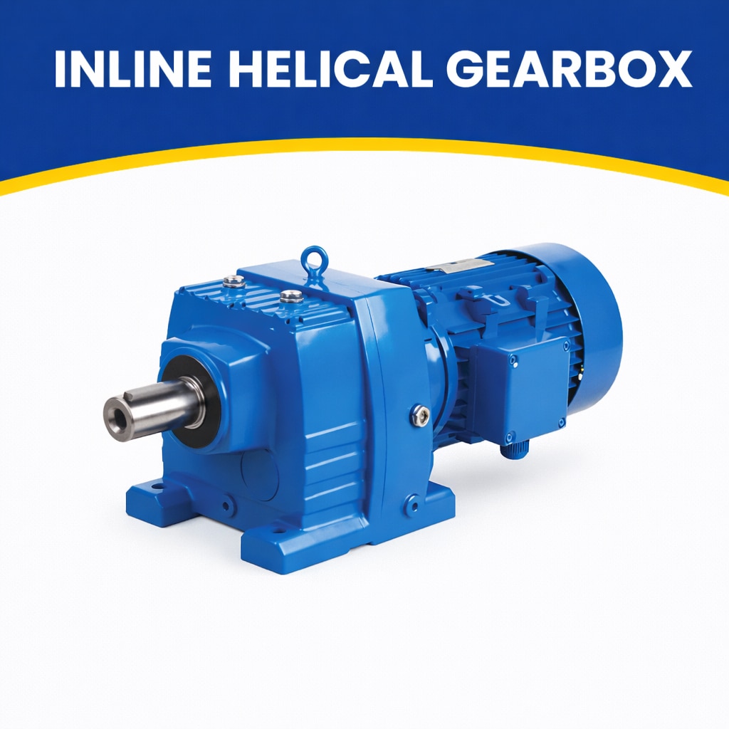 | Efficient & Compact Drive Solutions by JRB Engineering Works JRB Engineering Works manufactures high-quality Inline Helical Gearboxes designed for... View product → |
Frequently asked questions
Why is nameplate torque insufficient for selecting an industrial gearbox?
Nameplate torque shows a rated point, while continuous machinery experiences changing loads, speeds, starts and stops. Calculate T = 9,550P/n in newton-metres and check every operating point in the load spectrum.
How do you choose a gear arrangement for continuous heavy-duty operation?
Compare the required ratio, output torque, heat generation, load direction and machine layout. Helical, bevel, planetary and worm arrangements impose different efficiency, cooling and space requirements.
Which gear specifications affect load-carrying reliability?
Specify tooth material, case-hardening or through-hardening treatment, tooth geometry, face width, surface finish and the required contact and bending strength.
What operating checks protect gears after installation?
Verify bearing condition, lubricant grade and level, shaft alignment, vibration, noise and operating temperature against the supplier's documented limits.
Related products
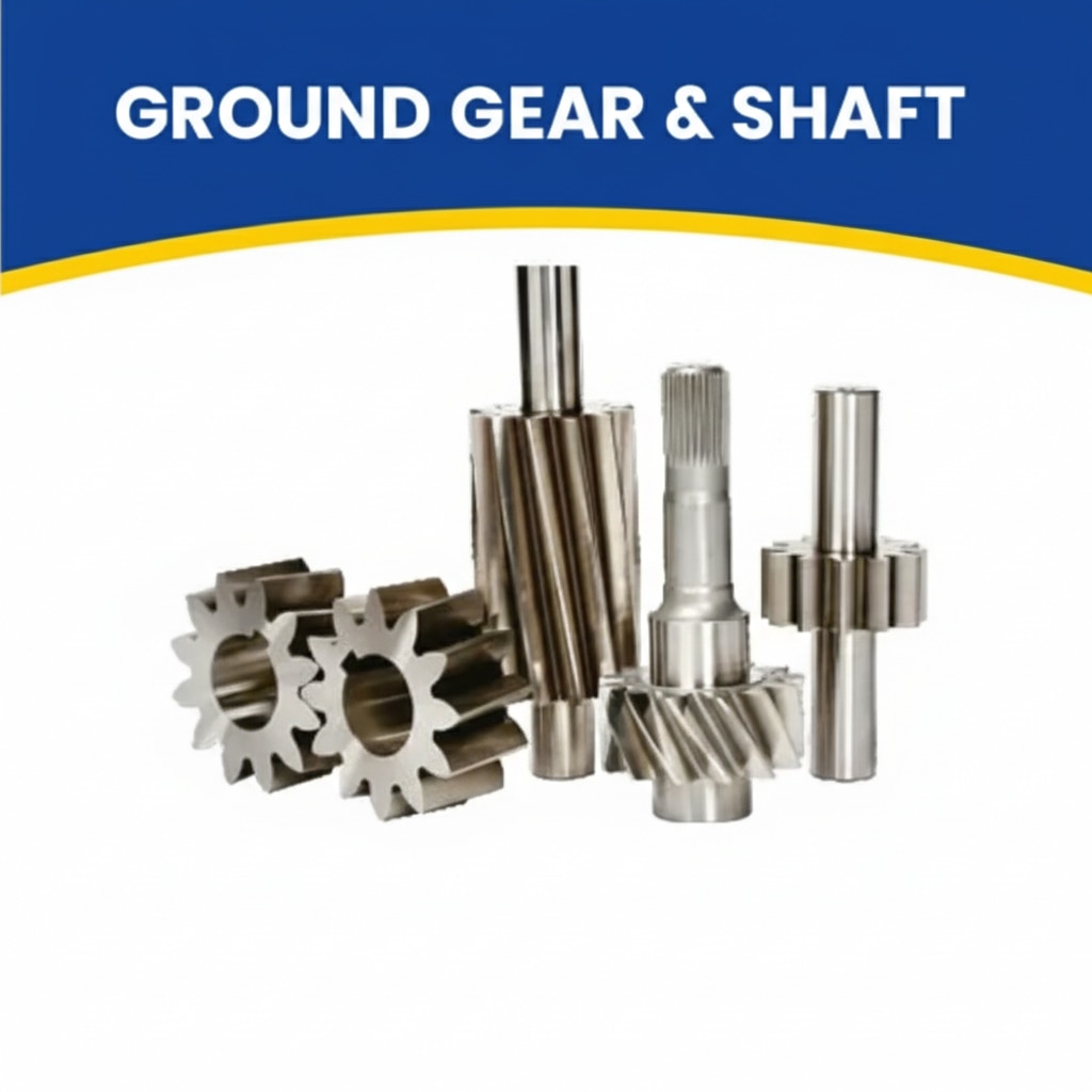 | at JRB Engineering Works JRB Engineering Works is a trusted manufacturer and supplier of high-precision Ground Gears and Shafts, engineered to... View product → |
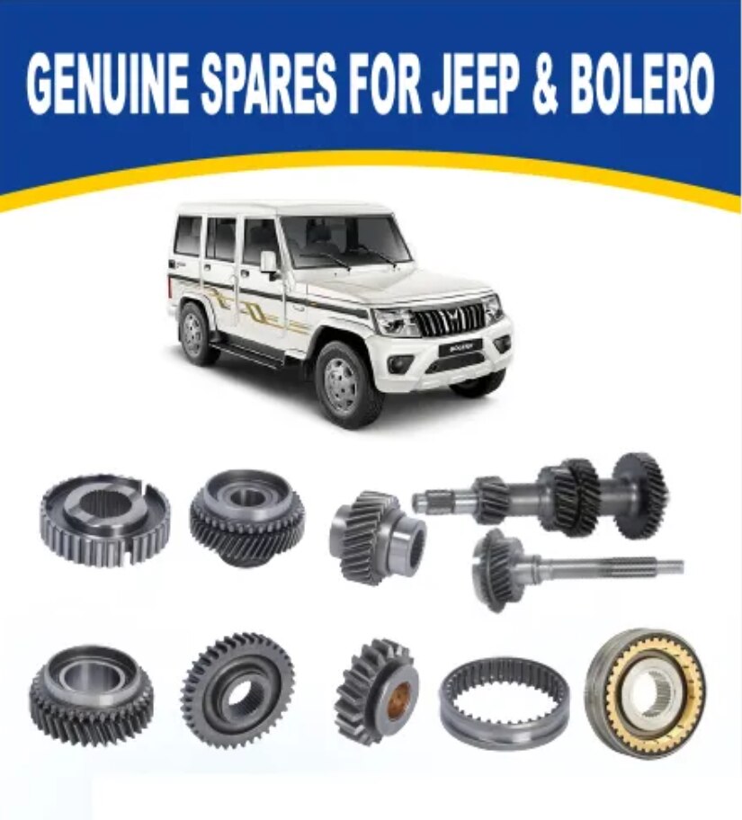 | We have technically qualified and efficient workforce, help us in manufacturing and supplying in Automotive Gears & Shaft. View product → |
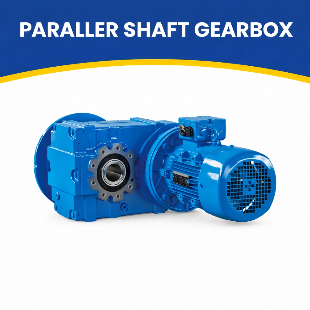 | High-Performance Power Transmission by JRB Engineering Works JRB Engineering Works manufactures and supplies Parallel Shaft Gearboxes designed for... View product → |
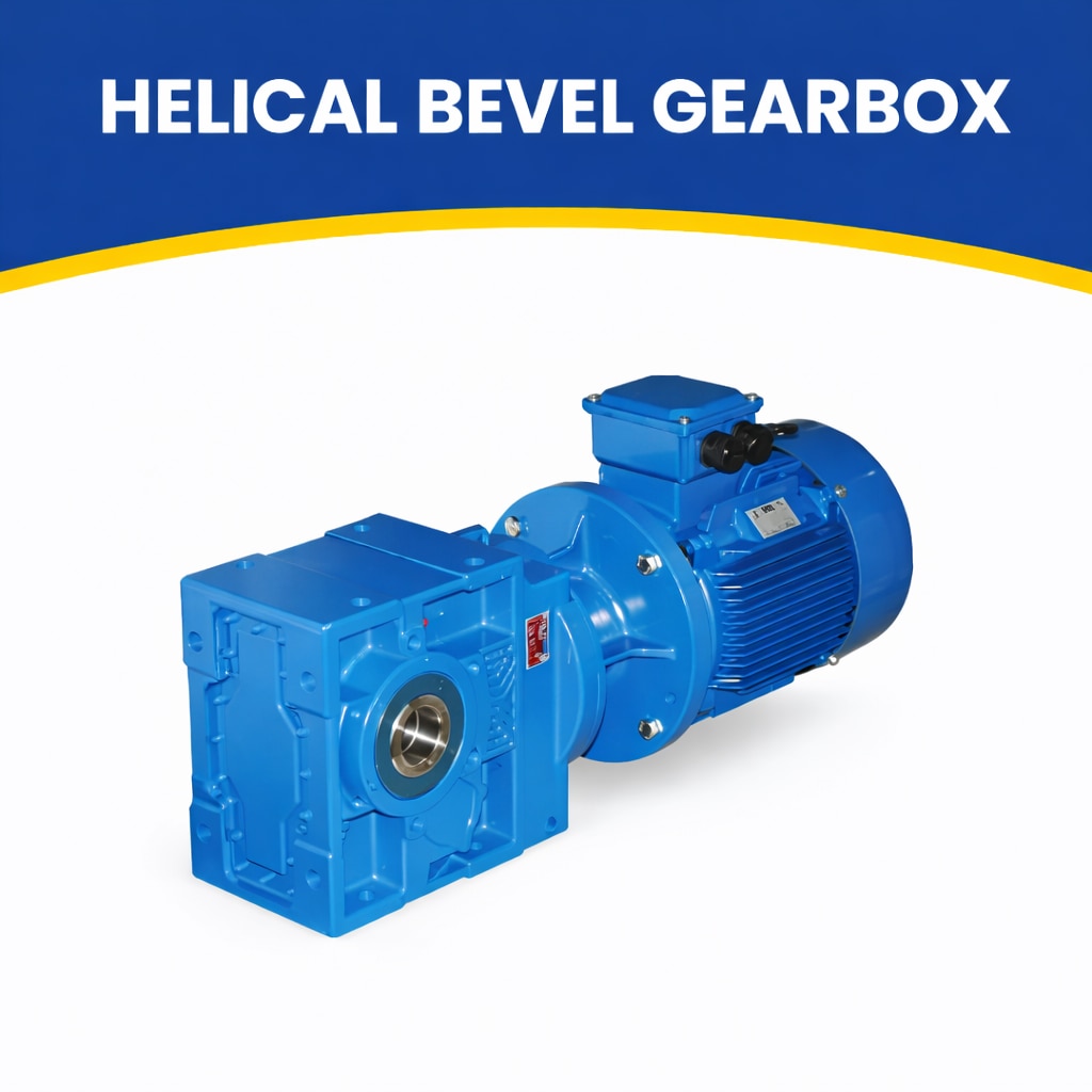 | High-Efficiency Right-Angle Drive Solutions by JRB Engineering Works JRB Engineering Works offers high-performance Helical Bevel Gearboxes designed... View product → |