Selecting an inline helical gearbox from motor power alone can produce a drive that overheats, lacks starting torque or fails under shaft loads. By defining speed, torque, duty, load type, interfaces and installation conditions, you can compare quotations on engineering evidence rather than catalogue claims.
Key takeaways
- Calculate output torque from speed, power and service factor.
- Match the gearbox to shock loads, starts per hour and driven-machine inertia.
- Confirm shaft dimensions, mounting position, motor frame and access clearances.
- Request one specification covering ratings, tolerances, tests and documentation.
Define the drive from speed, torque and duty data
Calculate the gearbox around output speed, output torque, and duty—not motor kW alone. Before ordering, define these inline helical gearbox requirements:
1. Record motor power and input speed, then state the required output speed. Calculate the reduction ratio as input speed ÷ output speed; do not confuse motor rpm with gearbox output rpm.
2. Calculate theoretical output torque with T = 9550 × P ÷ n, where T is torque in N·m, P is power in kW, and n is output speed in rpm. Apply the service factor to obtain design torque: calculated output torque × service factor.
3. Set the service factor from operating hours per day, starts per hour, starting or breakaway load, shock, reversing, cyclic loading, and variable-speed operation. A steady conveyor and an intermittently loaded mixer do not share the same factor because they have different load spectra.
4. Name the driven machine—such as a conveyor, pump, fan, mixer, compressor, or hoist—and state whether loading is constant, fluctuating, shock-loaded, or reversing. Gear teeth require checks for root bending and flank contact stress, not torque alone.
5. Calculate output-shaft radial and axial loads, including sprocket, pulley, or impeller weight and its distance from the bearing. These loads remain separate from output torque.
6. Check continuous thermal demand alongside mechanical rating, especially at low output speed, high ambient temperature, restricted airflow, or frequent starts. Request rated output torque, output speed, ratio, service factor, thermal limit, efficiency basis, and permissible shaft loads.
Match the gearbox to the driven machine and load pattern
The driven machine sets the gearbox rating because its load pattern, not motor kW alone, determines the torque demand. Specify output speed, output torque and motor power, then apply a service factor that reflects daily operating hours, starts per hour, reversals, cyclic duty and shock load.
Classify the driven machine before choosing the rating:
- A belt or chain conveyor with steady loading needs continuous-duty torque capacity, but account for loaded starting load and any jam-clearing torque.
- A mixer or agitator can impose high breakaway torque, cyclic resistance and shock load, demanding a higher service factor than a similarly powered conveyor.
- A pump or fan usually has a smoother load, yet frequent starts, variable-speed operation or operation near shutoff can change the torque and heating requirement.
- Rollers, packaging machines and other inline gearbox applications need the rating checked against acceleration, indexing, stopping and reversing cycles.
Check the gearbox’s mechanical rating against tooth-root bending and flank or contact stress for the actual load spectrum. Selecting by motor power alone can undersize the gears when torque peaks occur.
Mechanical capacity and thermal rating are separate limits. A gearbox can carry brief starting torque and still overheat during continuous duty, low output speed, high ambient temperature, restricted airflow or frequent starts.
Request permissible thermal power or the temperature basis at the stated duty, and include the mounting orientation because oil level and lubrication affect heat removal.
Compare inline helical performance with alternative gearbox layouts
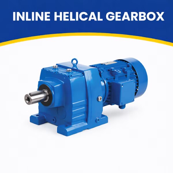
For a coaxial drive, an inline helical gearbox usually delivers the best balance of efficiency, smooth running and compact length. Choose another layout when the machine needs a 90-degree direction change, an offset low-profile drive, self-braking behaviour or unusually high starting torque.
| Option | Efficiency and heat | Footprint, noise and backdriving | Maintenance and best use |
|---|---|---|---|
| Inline helical gearbox | High efficiency when correctly rated; verify multi-stage efficiency at the actual speed, ratio, load and temperature | Coaxial, smooth and relatively quiet; normally backdrives, so it cannot be treated as a brake | Straightforward oil and seal service; strong choice for conveyors, rollers, pumps, fans and packaging machinery |
| Worm gearbox | More sliding loss, especially at high ratios; heat can limit continuous duty | Compact and quiet with a right-angle output; some combinations resist backdriving, but never assume self-locking | Check oil temperature and lubrication closely; useful where cost, right-angle mounting or holding action outweighs efficiency |
| Helical bevel gearbox | Efficient right-angle transmission, with losses depending on stages and ratio | Changes direction without the larger offset of some layouts; noise remains low when aligned correctly | More components and interfaces to inspect; choose it when the motor and driven shaft must meet at 90 degrees |
| Parallel-shaft gearbox | Efficient for high torque and conveyor duty | Low-profile, offset arrangement; not suitable when input and output must be coaxial | Accessible on many conveyor installations; needs space beside the driven shaft |
The main inline helical gearbox benefits disappear if indexing requires low backlash, high torsional stiffness or repeatability. Make a worm gearbox comparison using measured efficiency, output temperature, backlash and peak torque, not catalogue labels alone. For every option, confirm service access, breather position, seals and lubricant for dust, humidity and heat.
Check shafts, mounting, motor fit and service access
Verify the shaft interface, mounting orientation, motor adaptor and service clearances before approving the gearbox. Choose a solid output shaft or hollow output shaft to suit the driven machine, then check shaft diameter, keyway, usable length, bore tolerance, coupling fit and any shrink-disc or torque-arm requirement.
| Interface | Verify before ordering | Failure if missed |
|---|---|---|
| Solid output shaft | Coupling bore, key size, shaft extension and alignment | Coupling will not fit or will impose bending load |
| Hollow output shaft | Driven-shaft diameter, keyway, insertion length and retention method | Hub slips, bottoms out or cannot be removed |
| IEC motor frame | Frame size, flange and pilot dimensions, shaft extension, key dimensions and motor mass | Motor fits the nameplate power but not the adaptor |
| Output loading | Radial and axial loads, load position and overhung distance | Pulley, sprocket or impeller overloads the bearings |
Confirm that the adaptor’s permissible input speed and overhung load exceed the motor and coupling conditions. A matching IEC motor frame does not make every motor of the same kW mechanically interchangeable.
State the mounting orientation at purchase: horizontal, vertical-output or another specified position. Orientation changes oil level, breather location, bearing lubrication and thermal limits; an incorrect position can cause leakage or bearing damage.
Before commissioning, check:
- Provide service space to remove the breather, inspect seals, drain oil and withdraw the motor.
- Use the specified lubricant viscosity, fill level and seal-compatible oil; do not mix oil types.
- Confirm the manual states mounting position, oil-change interval, noise value and protection provisions.
- Align shafts, tighten feet or flanges, and verify free rotation before connecting the load.
Turn the requirements into a comparable procurement specification
Send every bidder the same duty schedule and require a completed gearbox datasheet, not a quotation based only on motor kilowatts.
Your request for an inline helical gearbox for requirements in New Delhi should identify the driven machine, output speed, output torque, motor power and speed, reduction ratio, duty cycle, starts per hour, operating hours and service factor.
Require the power transmission equipment manufacturer to state these fields for the proposed unit:
- Mechanical rating, thermal rating, permissible thermal power, and the ambient-temperature basis; state your design ambient range instead of accepting an assumed 40°C.
- Efficiency basis, rated output torque, output speed, permissible radial and axial shaft loads, backlash, torsional stiffness and peak torque where reversing, indexing or positioning applies.
- Mounting position, shaft arrangement, flange and pilot dimensions, key sizes, IEC motor frame compatibility, adaptor input-speed limit, motor mass limit and overhung-load limit.
- Lubricant grade, fill quantity, breather location, drain and inspection access, operating noise value, paint system, sealing provisions and enclosure rating under IEC 60529.
- Applicable design and test standards, inspection records, warranty conditions, delivery scope, spare parts and commissioning requirements.
Ask OPTIGEAR to return this schedule with each quotation so price differences are not mistaken for technical equivalence. Reject any offer that omits the thermal limit, load capacities, ambient basis or motor-interface dimensions; those omissions prevent a fair comparison and create installation risk.
Related product
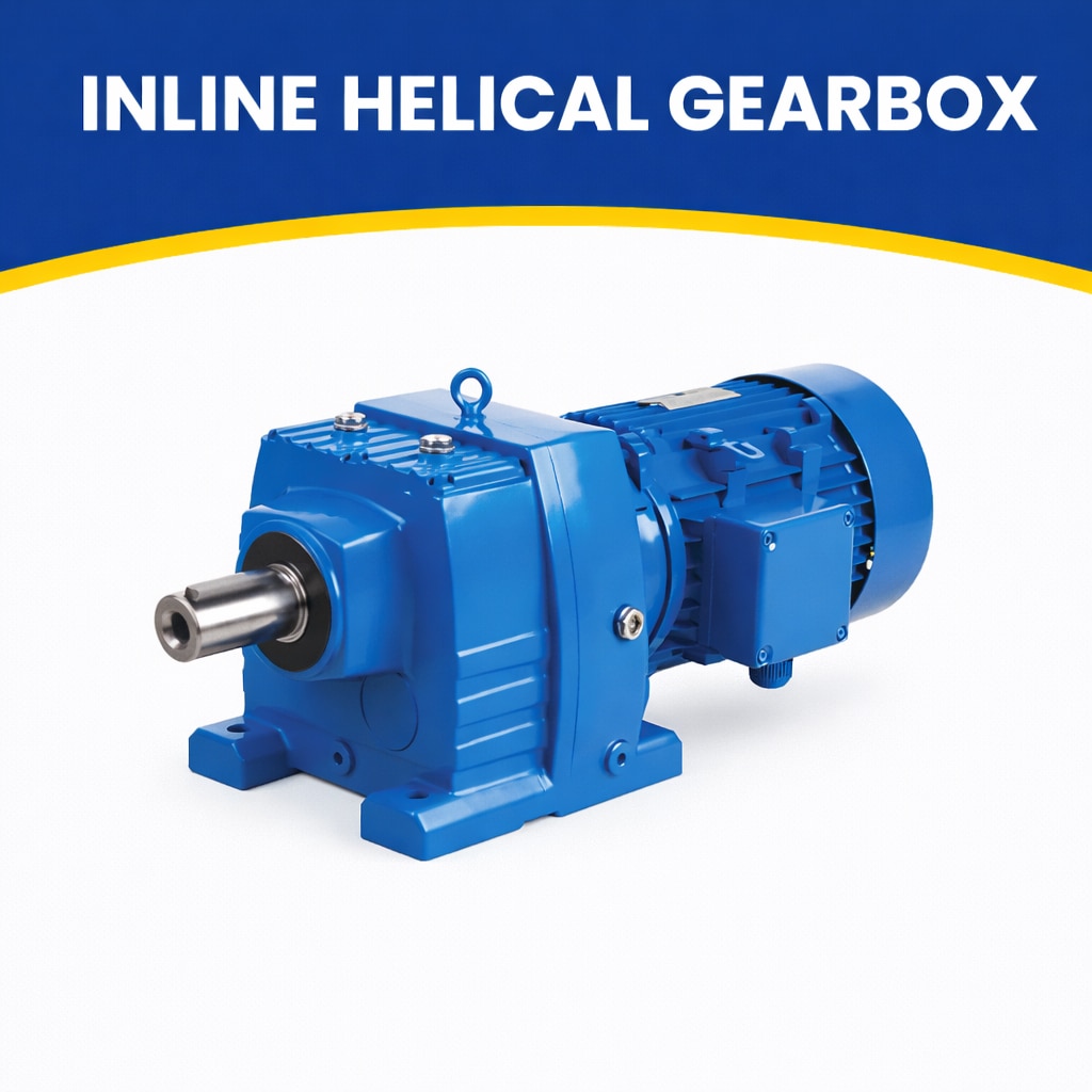 | Efficient & Compact Drive Solutions by JRB Engineering Works JRB Engineering Works manufactures high-quality Inline Helical Gearboxes designed for... View product → |
Frequently asked questions
What data do you need to size an inline helical gearbox?
Provide required output speed, output torque, operating hours, starts per hour, load pattern, ambient conditions and the motor’s rated power. Size from output torque and duty rather than motor kW alone.
Which load factors affect an inline helical gearbox selection?
Shock loads, reversing, frequent starts, driven-machine inertia, daily operating hours and the required service factor affect selection. A conveyor with steady load needs a different rating from a crusher with impact loading.
How does an inline helical gearbox compare with other layouts?
Inline helical gearboxes keep input and output shafts on one axis and deliver efficient, quiet reduction in compact drives. Parallel-shaft, bevel-helical and worm layouts suit different offset, right-angle, ratio and efficiency requirements.
What should an inline helical gearbox procurement specification include?
State output speed, continuous and peak torque, ratio, duty class, service factor, motor frame, shaft size and extension, mounting orientation, lubricant, seals, ambient conditions, noise limits, inspection tests and required drawings.
Keywords