A motor does not drive a conveyor, pump or mixer by itself: torque and speed pass through a connected chain of couplings, shafts, belts, gears and reducers. By the end, you will be able to identify each component’s job, calculate the basic drive requirements, specify compatible equipment and spot the operating conditions that make a standard arrangement unsuitable.
Key takeaways
- Match each component to torque, speed, load pattern and operating environment.
- Check gearbox service factor, output torque, speed and thermal rating before purchase.
- Specify V-belts by profile, length, power demand and environmental exposure.
- Prevent failures with correct alignment, tension, lubrication and scheduled inspections.
What power transmission equipment does in an industrial machine
The power transmission equipment definition is simple: it carries rotating power from a source to the part that performs work. The prime mover, such as an electric motor or engine, supplies rotation.
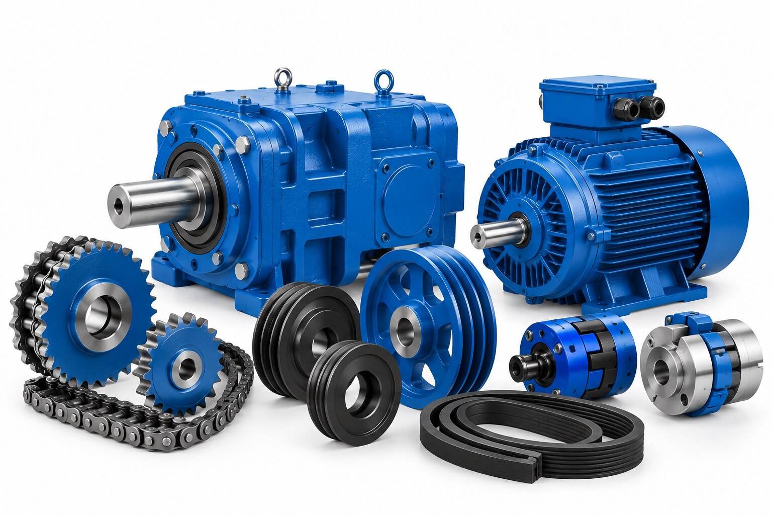
A coupling joins its shaft to another shaft; the gearbox changes speed and torque; the shaft carries torque onward; and a shaft and pulley, belt drive, or gearset transfers motion to the driven machine, such as a conveyor, pump, fan, or mixer.
The gearbox role in machinery analysis is to match the motor’s speed and torque to the load’s requirements.
Power generation versus transmission is the difference between creating power and delivering it to a load. Power generation creates electrical or mechanical power, while electrical transmission moves electrical energy through conductors and transformers. Hydraulic systems transmit force through pressurised fluid, and pneumatic systems use compressed air.
These systems can work together, but each solves a different part of the machine’s power path.
| System | Main energy form | Function |
|---|---|---|
| Power transmission equipment | Rotation | Carries torque to a driven machine |
| Electrical transmission | Electricity | Moves energy through conductors and transformers |
| Hydraulic systems | Pressurised fluid | Transmits force through fluid |
| Pneumatic systems | Compressed air | Transmits force through air |
How to choose between belts, chains, gears, shafts, couplings and gearboxes
| Option | Function and strengths | Limits and checks |
|---|---|---|
| V-belts | Economical, quiet speed transfer; absorb shock and tolerate flexible centre distance | Slip and belt tension trade-offs; check wrap, sheave size and belt speed |
| Chains | Positive engagement for moderate-to-high torque; no normal slip | Noise, lubrication and polygonal speed variation require acceptance |
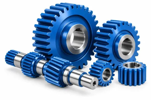
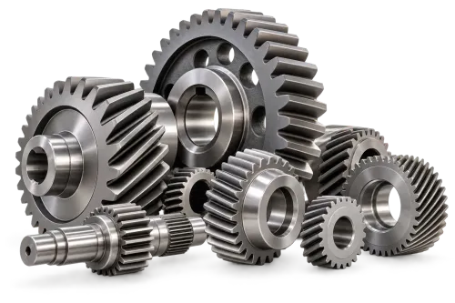
| Spur and helical gears | Compact, precise ratios and high torque; helical gears run more smoothly | Check backlash, tooth loading, lubrication and alignment |
| Shafts | Carry torque while resisting bending; size for combined loading | Shafts and torsional stress require attention to keyways, shoulders and grooves, which concentrate fatigue stress |
| Couplings | Connect shafts and transmit torque while accommodating rated angular, parallel and axial misalignment | A flexible coupling does not permit arbitrary misalignment; check peak torque, speed, bore and key |
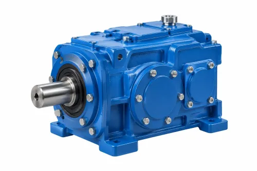
| Gearboxes | Provide gearbox reduction ratio when motor speed must fall or torque must increase | Check mechanical and thermal ratings, service factor and output arrangement |
For the torque speed power relationship, use T = 9,550P/n, in N·m, with P in kW and n in r/min. A 15 kW motor at 1,500 r/min produces about 95.5 N·m. On a conveyor, a 5:1 reducer gives about 300 r/min and approximately 477 N·m before efficiency, service-factor and rating checks.
Selection still depends on starting torque, overload peaks, duty cycle, starts, reversals and speed variation. Motor power alone cannot size the belt, chain, gearset, shaft or reducer.
How to select a gearbox and check its usable rating
Use this gearbox selection method: record motor power, input speed, required output speed, calculated torque, load type, duty cycle, starts per hour, reversals, mechanical service factor and environment. Calculate torque with T = 9,550P/n, then check shock loads, starts and stops, overhung load, thermal rating, low-speed cooling and continuous-duty limits.
- Treat nominal mechanical torque as a strength limit, not usable continuous torque. Compare the manufacturer’s mechanical rating with thermal capacity at your actual speed and duty; low-speed cooling can restrict continuous operation before tooth or shaft strength does.
- Do not transfer a service factor between manufacturers. Load classification, operating hours, starts per hour and shock definitions differ, so one mechanical service factor does not mean the same usable margin.
- Check ISO 1328 gear accuracy separately from gear load capacity. Accuracy covers profile, lead and pitch deviations; capacity depends on tooth size, width, material, heat treatment, hardness, lubrication and duty.
- Specify backlash as designed clearance. Too little risks seizure during thermal growth; too much causes impact, noise, positioning error and edge loading. A worm gearbox backdriving check still needs a rated brake when reverse motion is safety-critical.
| Configuration | Fit | Wrong choice |
|---|---|---|
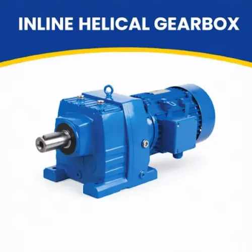
| Inline helical gearbox | Coaxial shafts; compact straight mounting direction and output arrangement | Fails when output must turn 90 degrees |
| Parallel shaft gearbox | Offset shafts; useful where mounting direction and side output orientation suit limited width | Wastes space when coaxial mounting is required |
| Helical bevel gearbox | Right-angle shafts and matching output orientation | Unsuitable when its right-angle arrangement cannot match the machine |
Standard equipment is a poor fit for severe shock loading, frequent reversing, explosive atmosphere, extreme temperatures, corrosive washdown or precise positioning without purpose-built design and safety devices.
How to specify a V-belt drive and protect it from the environment
Specify a V-belt drive with:
- belt section or profile, effective length, number of belts, pulley diameter, centre distance, wrap angle, speed ratio, belt speed and manufacturer’s belt tension range.
A small pulley increases bending fatigue, shortening belt life. Insufficient wrap angle reduces contact and power capacity. In a matched belt set, never mix different lengths, profiles, manufacturers or wear states; load shifts onto fewer belts. Set belt tension with the maker’s force-deflection or frequency method, not by hand.
Over-tension raises shaft and bearing loads; under-tension causes slip, heat and glazing.
| Drive type | Advantage | Main failure risk |
|---|---|---|
| V-belt | Friction drive with economical shock absorption | Slip under load |
| Synchronous belt | No normal steady-state slip | Synchronous belt tooth jumping from inadequate pretension, overload, abrupt acceleration, eccentric pulleys or excessive centre distance |
Protect belts, seals, bearings, gears and lubricants from dust and moisture, heat, chemicals, outdoor exposure and washdown. Choose oil versus grease by speed, sealing and manufacturer guidance; confirm lubricant viscosity or grade, fill level, breather location and inspection interval. Overfilling gearbox oil causes heat and foaming.
Verify additive compatibility with bronze worm wheels, seal materials and painted interiors.
How installation and maintenance prevent transmission failures
1. Before contact, use lockout/tagout, block stored energy, control stored belt tension, complete guarding, and verify zero movement. Use rated equipment when lifting gearbox units.
2. Commission for power transmission installation errors: check shaft alignment, coupling bore and key fit, pulley runout, mounting bolts, rotation direction, gearbox oil level and breather position. A flexible coupling accepts only its rated misalignment; arbitrary misalignment creates heat and bearing loads. Unsupported overhung loads can overload bearings and shafts.
Confirm balance grade, key convention, and assembled-rotor balance as speed rises.
3. Schedule visual checks, belt-tension checks, bolt checks, lubrication inspection, vibration monitoring, temperature checks, oil inspection, and alignment verification. Balance matters more at high speed because unbalance force rises with the square of rotational speed.
4.
Map symptoms before replacing parts: rising temperature indicates overload, wrong viscosity, overfilling or blocked breathers; oil leakage indicates seals, plugs or excessive fill; tooth noise indicates backlash, wear, contamination or misalignment; belt slip indicates low tension, overload or poor wrap; belt cracking indicates heat, chemicals, age or small pulleys; shaft vibration indicates imbalance, bent shafts, misalignment or loose fits; bearing noise indicates lubrication failure, contamination or overload; output-speed loss indicates slip, incorrect ratio or damaged teeth.
How to verify compatibility, compare suppliers and decide what to replace
Read the equipment nameplate and dimensional drawing before ordering. Record input and output shaft diameters, keyway and key size, mounting holes, flange, output orientation, ratio, rated torque, input speed and rotation direction. These values define replacement compatibility.
Match shaft diameter, key, centre distance, pulley profile, belt length, gearbox mounting pattern, output speed and load direction. A near match can bind, slip or reverse the load.
| Option | Downtime and work | Main risk |
|---|---|---|
| Repair | Least downtime and alignment work; lifting access is usually minimal | Spare-part availability and hidden damage |
| Component replacement | Moderate downtime, alignment and commissioning effort | An unverified substitute |
| Complete gearbox replacement | Greatest downtime; confirm lifting access and mounting fit | Full commissioning and new alignment |
For supplier documentation, request a dimensional drawing, performance data, material and heat-treatment information where relevant, tolerances, lubrication instructions, maintenance schedule, test records, warranty terms and after-sales support. OPTIGEAR is one supplier you can ask for these missing technical documents.
Reject “high performance” and “long life” without traceable ratings, dimensions, tolerances and test evidence. Available product copy leaves technical data gaps: torque ratings, ratios, speed ranges, dimensions, materials, efficiency, temperature limits, noise, protection ratings, standards, test methods, delivery and maintenance information.
Related products
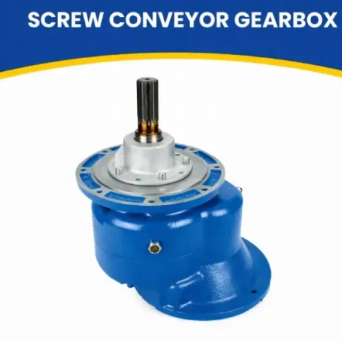
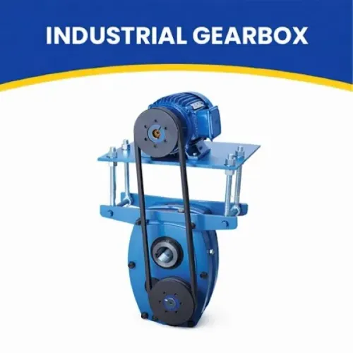
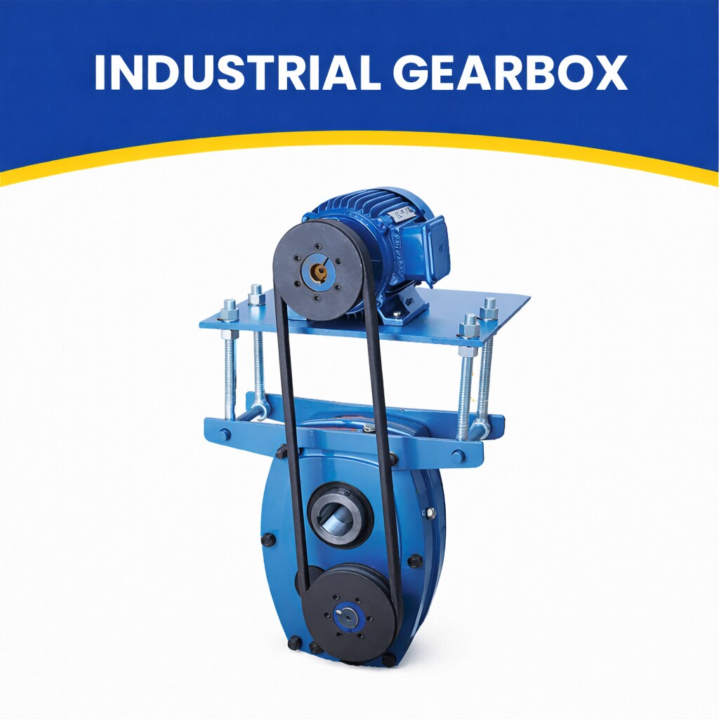 | By JRB Engineering Works JRB Engineering Works is a trusted manufacturer and supplier of high-performance Industrial Gearboxes, engineered to deliver... View product → |
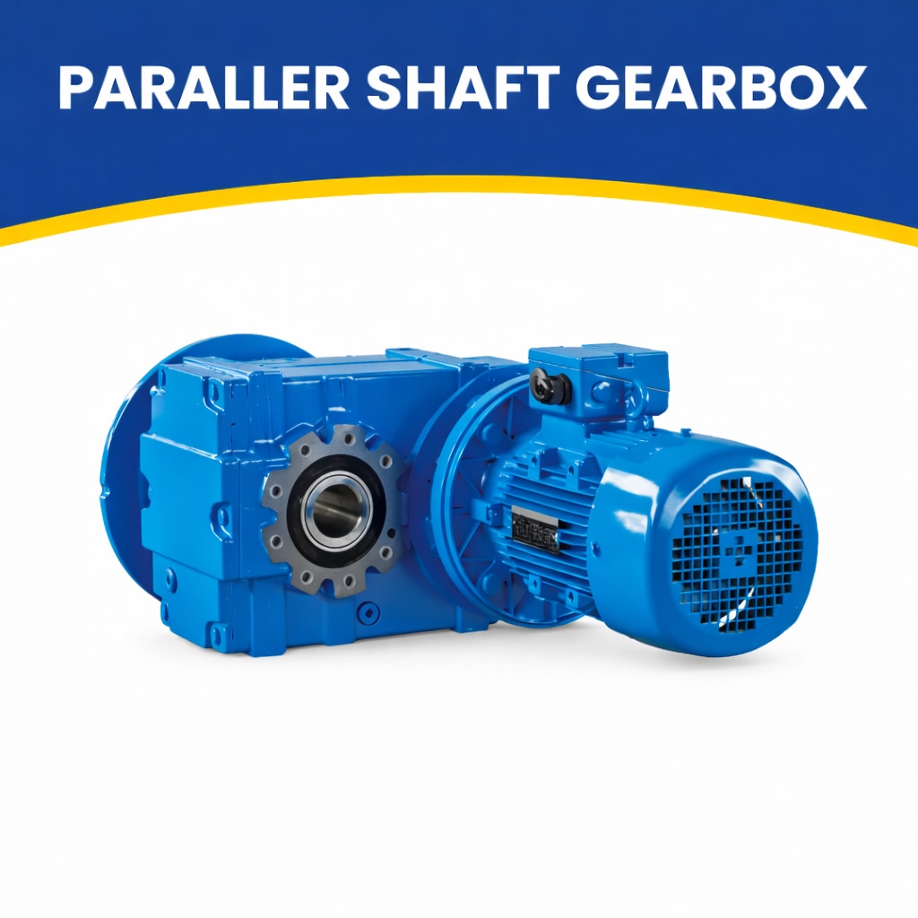 | High-Performance Power Transmission by JRB Engineering Works JRB Engineering Works manufactures and supplies Parallel Shaft Gearboxes designed for... View product → |
Frequently asked questions
What does power transmission equipment do in an industrial machine?
It transfers rotation and torque from a motor or engine to the machine component that performs work.
How do you choose between belts, chains, gears, shafts, couplings and gearboxes?
Compare required torque, speed ratio, centre distance, shock load, alignment, efficiency, noise, maintenance and environmental conditions.
How do you select a gearbox and check its usable rating?
Check input speed, output speed, output torque, service factor, thermal capacity, duty cycle, mounting arrangement and allowable overhung load.
How do you specify and protect a V-belt drive?
Specify the belt section, pitch length, pulley sizes, centre distance and power requirement, then protect the drive from heat, oil, dust and misalignment.
How do installation and maintenance prevent transmission failures?
Use correct alignment, belt tension, lubrication, fastening and guarding, then inspect wear, vibration, temperature and noise on a planned schedule.
Related products
 | JRB ENGINEERING WORKS is equipped with latest machines with a separate tool room arrangement. View product → |
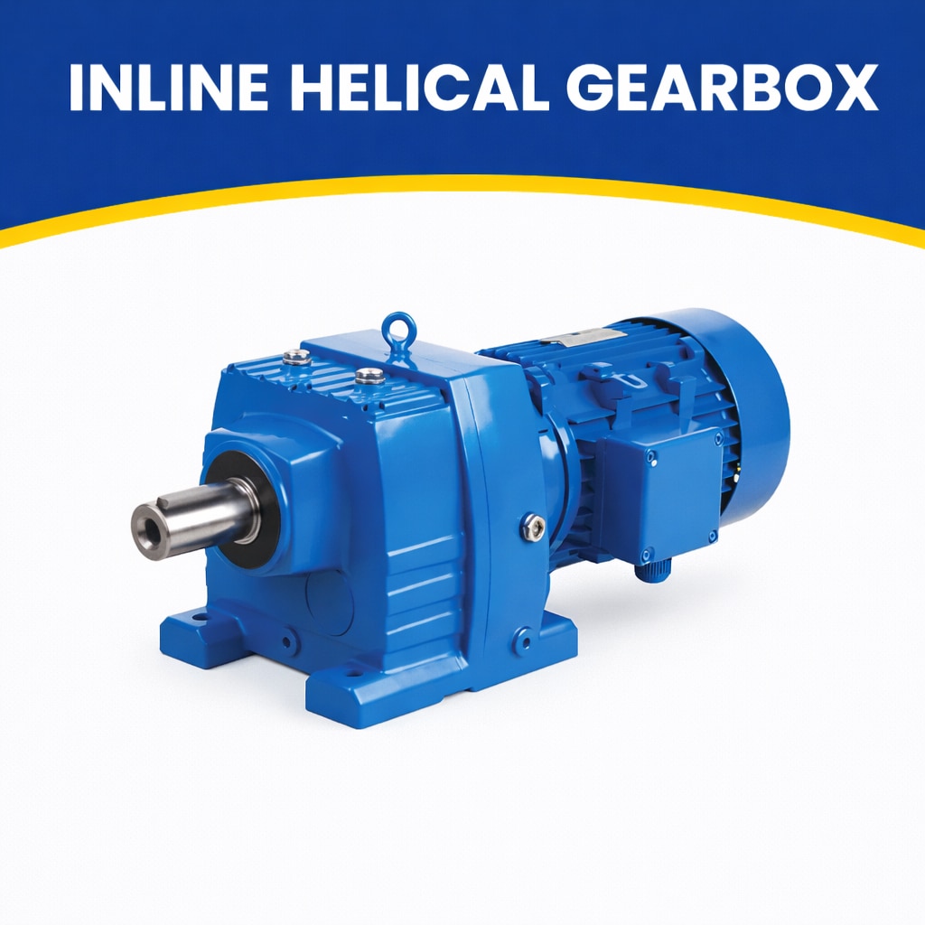 | Efficient & Compact Drive Solutions by JRB Engineering Works JRB Engineering Works manufactures high-quality Inline Helical Gearboxes designed for... View product → |
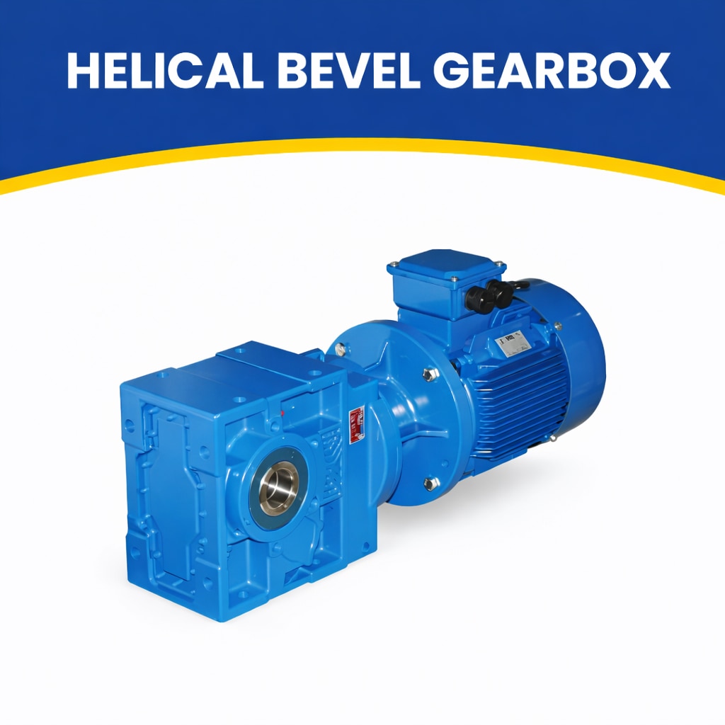 | High-Efficiency Right-Angle Drive Solutions by JRB Engineering Works JRB Engineering Works offers high-performance Helical Bevel Gearboxes designed... View product → |
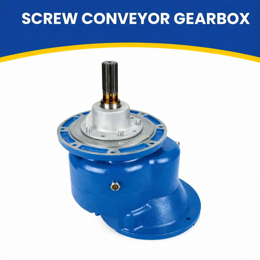 | By JRB Engineering Works Optigears is the world’s top manufacturer of screw conveyors and feeders. View product → |