A gearbox can contain accurately made teeth and still run noisily, lose efficiency or fail early when heat treatment, shafts, bearings and housing alignment are overlooked. By following the manufacturing sequence and matching each tolerance to the machine’s load and speed, you can distinguish useful precision from expensive over-specification.
Key takeaways
- Control each machining stage to protect tooth geometry and contact patterns.
- Compare pitch, runout, profile and helix measurements before approving a gear.
- Choose grinding or honing when noise, load, finish or accuracy justify the extra work.
- Match gear and shaft tolerances to the drive’s speed, load and operating conditions.
How the Manufacturing Process Builds Gear Accuracy
Final gear accuracy is built by controlling every stage before the teeth reach inspection. Each operation protects tooth geometry, strength, surface finish and the contact pattern that determines noise, load capacity and service life.
1. Gear blank preparation establishes the reference surfaces. Accurate turning controls bore size, face squareness and outside diameter, while balanced material prevents eccentricity and once-per-revolution vibration.
2. CNC hobbing generates consistent tooth spacing and form on external gears. CNC shaping handles internal gears and restricted geometries, producing the specified tooth profile and lead before hardening.
3. Heat treatment raises resistance to tooth-root fatigue and flank wear, but uneven cooling can distort the gear. Heat treatment allowance control reserves the material left for later machining, so grinding can remove distortion without cutting below the required geometry.
4. Grinding restores hardened flanks to tighter profile, lead and pitch limits. Honing removes fine machining marks and improves surface contact; both processes require controlled stock removal and protection against grinding burn.
5. Deburring removes sharp edges that could damage bearings, seals or mating teeth. Final inspection then checks tooth geometry, runout, bore relationship and surface finish against the drawing and a named system such as ISO 1328.
A precise gear still needs correct center distance, shaft alignment, bearing clearance and backlash. Tight tolerances cannot rescue a distorted housing or excessive interference, and insufficient backlash can create heat, seizure and premature failure.
Which Measurements Prove That a Gear Is Accurate?
A gear is proven fit for service by a controlled inspection report, not by outside diameter alone. Request the ISO 1328 accuracy grade or AGMA quality number, inspection temperature, datum strategy and measurement method, such as a calibrated gear analyser or coordinate-measuring machine.
| Measurement | What it reveals | Evidence to request |
|---|---|---|
| Tooth profile deviation | Departure from the intended involute, which can cause impact, noise and uneven load sharing | Profile chart with measured and permissible values |
| Lead deviation | Flank direction error across the face width, which can create edge loading | Lead or helix chart, including face-width location |
| Pitch error | Unequal tooth spacing, producing tooth-to-tooth mesh variation and transmission error | Single-pitch and cumulative-pitch results |
| Runout and concentricity (alignment of rotating features) | Once-per-revolution excitation from an eccentric gear or bore | Radial runout record and datum-referenced concentricity result |
Read the numbers alongside the charts. A spectrum showing a strong once-per-revolution component points to runout or eccentricity; pitch errors appear at mesh-related frequencies and as sidebands. Better average pitch alone will not remove that excitation.
Ask for the measurement reference diameter, probe alignment and temperature correction. A result taken away from the stated datum or at a temperature other than the report’s reference, commonly 20°C, can make an accurate gear appear faulty—or hide a real error.
Finally, request the assembly contact pattern or loaded tooth-contact analysis. ISO 1328 does not prove tooth strength, lubrication, bearing alignment or housing stiffness, and an acceptable static pattern can become edge contact under torque and heat.
Cut, Ground or Honed: When Is Extra Finishing Worth It?
Cut gears are usually enough when the drive runs at moderate speed, carries a predictable load and has tolerance for more noise or backlash.
Grinding earns its extra machining time after hardening has distorted the teeth or when the required ISO 1328 accuracy grade, the international gear-accuracy classes, demands tighter profile, lead, pitch or runout control.
Choose grinding or honing over cut gears when:
- A high-speed gearbox needs lower mesh excitation, because corrected flank geometry reduces pitch-related vibration and speed-related noise.
- Heat treatment has left measurable profile or helix distortion, because grinding removes controlled stock and restores the intended tooth form. Specify stock allowance before hardening; excessive removal or grinding burn can weaken the flank.
- The application needs a smoother, more stable contact surface, where honing improves surface roughness and removes small high spots after hardening without the stock removal of grinding.
Ground gears suit demanding accuracy and load-sharing requirements; honed gears suit hardened gears that already have near-correct geometry but need smoother engagement. Honing cannot rescue major runout, incorrect tooth form or a badly distorted gear.
Do not approve the upgrade from an accuracy grade alone. ISO 1328 does not prove bending strength, pitting resistance, scuffing resistance, lubrication or housing stiffness. A ground gear can still fail if the material, heat treatment, bearing alignment or loaded contact pattern is wrong.
Check gear rating and loaded tooth contact before paying for tighter finishing.
Match Gear and Shaft Precision to the Working Drive
Choose gear and shaft tolerances from transmitted torque, speed, reduction ratio and duty cycle—not from the tightest available grade. A fast, continuously loaded reducer needs tighter runout, pitch and lead control than an intermittent, low-speed drive, while shock loads demand stiffness and tooth strength as much as dimensional accuracy.
| Drive condition | Gear and shaft choice | Main check |
|---|---|---|
| Low speed, intermittent load | Standard cut gears; moderate shaft runout tolerance | Confirm torque capacity and acceptable backlash |
| Continuous moderate speed | Tighter pitch, profile and lead control; controlled shaft concentricity | Check temperature, noise and contact pattern |
| High speed or positioning drive | Ground teeth, low runout shafts and closely controlled backlash | Analyse transmission error and once-per-revolution excitation |
| High torque or shock load | Prioritise tooth strength, shaft stiffness and loaded alignment | Verify contact under peak torque, not only at assembly |
Backlash is functional clearance between mating teeth. It leaves room for lubricant films, thermal expansion and assembly variation; reduce it too far and interference, heat or seizure can result, while excessive clearance causes impact and lost positioning accuracy.
Ask for loaded tooth-contact analysis when torque, temperature or housing deflection can move the contact toward an edge. Check shaft straightness, bearing clearance, centre distance, parallelism and squareness because precise teeth cannot correct poor alignment.
Profile tip relief can reduce mesh-force fluctuation and noise, but excessive relief removes working contact and raises stress at the relief boundary. OPTIGEAR can help compare gear-and-shaft specifications against the drive’s actual load and alignment limits rather than selecting tolerances in isolation.
Related products
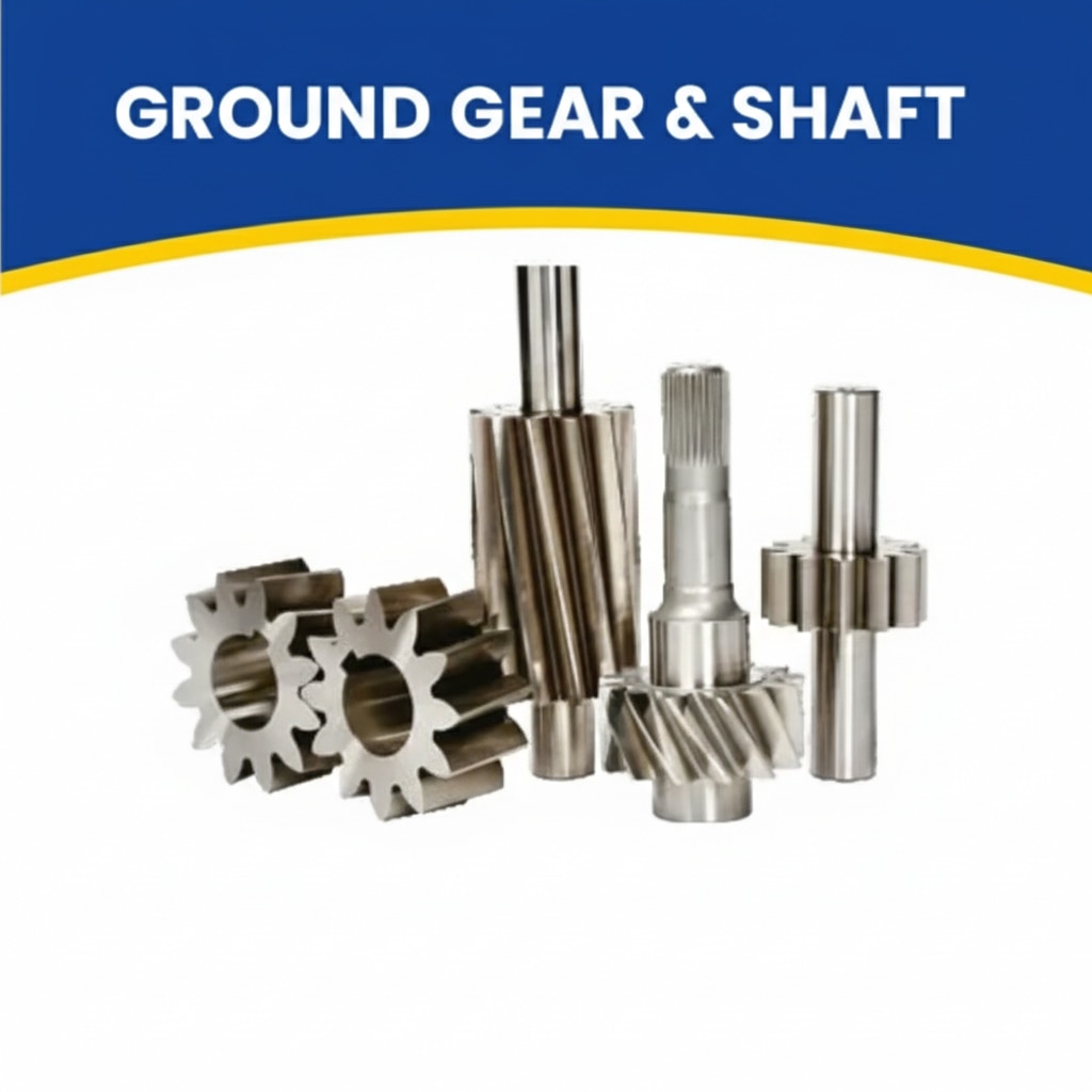 | at JRB Engineering Works JRB Engineering Works is a trusted manufacturer and supplier of high-precision Ground Gears and Shafts, engineered to... View product → |
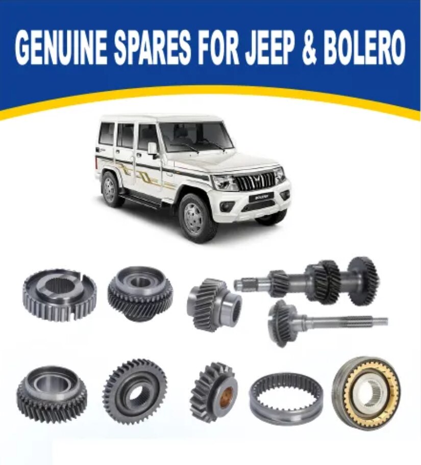 | We have technically qualified and efficient workforce, help us in manufacturing and supplying in Automotive Gears & Shaft. View product → |
What Precision Gears Change in Real Machine Performance
Precision gears usually reduce mesh noise and vibration because tighter pitch, profile and runout control keeps tooth contact more consistent. The gain is greatest at high speed, where a small spacing error becomes a repeated impact.
Lower-cost gears can perform well at modest speed, but their greater variation can increase tonal noise, bearing load and housing movement.
| Performance area | Standard lower-cost gear | Precision gear |
|---|---|---|
| Noise and vibration | More mesh variation; louder as speed or load rises | Smoother contact and lower excitation when alignment is correct |
| Efficiency | Losses increase through sliding, friction and misalignment | Lower tooth friction, but the improvement is not automatically large |
| Service life | Greater local stress can accelerate pitting, wear or tooth damage | More even load sharing can extend fatigue life |
| Replacement risk | Early wear or inconsistent interchangeability can trigger downtime | Better repeatability reduces fit and early-failure risk |
Do not treat a high AGMA quality number as proof of a durable gearbox. Lubricant viscosity, oil churning, seals, bearings, preload, temperature, housing stiffness and shaft alignment can outweigh tighter tooth tolerances. Excessively smooth surfaces can also retain less lubricant; specify surface roughness with its parameter and measurement direction.
For a purchasing decision, request coordinate-measuring-machine reports and gear measurement charts showing profile, lead, pitch and runout results, plus the inspection temperature and datum method. Compare the stated AGMA quality numbers with the machine’s speed and load, not with price alone. A precision gear cannot correct a bent shaft, wrong centre distance or misaligned housing.
Frequently asked questions
How does the manufacturing process build gear accuracy?
Accuracy comes from controlling material preparation, tooth cutting, heat treatment, finishing and final inspection so tooth geometry and contact remain consistent.
Which measurements prove that a gear is accurate?
Check pitch error, radial runout, tooth profile deviation, helix deviation, surface finish and the final tooth contact pattern.
When is grinding or honing worth the extra finishing?
Use extra finishing when the drive needs tighter geometry, lower noise, smoother contact, improved surface finish or reliable performance under demanding loads.
How should gear and shaft precision match the working drive?
Set tolerances against the drive’s speed, transmitted load, alignment, duty cycle, lubrication and operating environment rather than choosing the tightest class automatically.
Related product
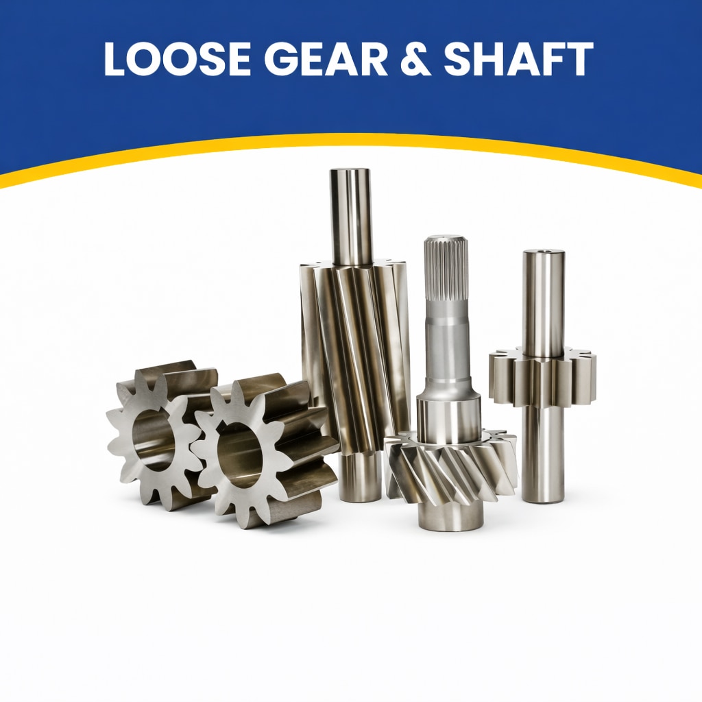 | Precision Components by JRB Engineering Works JRB Engineering Works is a trusted manufacturer and supplier of Loose Gears & Shafts, engineered to... View product → |