A gearbox must match more than the motor’s kilowatt rating: speed, torque peaks, heat, mounting, shaft loads and the driven machine all affect whether the selection will survive. By working through the application data, calculations, gearbox types and fit checks in order, you can request comparable quotations and reject ratings that look adequate only on paper.
Key takeaways
- Calculate ratio from machine speed, not motor power alone.
- Check continuous, peak and thermal torque ratings before approving a gearbox.
- Match the arrangement to efficiency, available space and load behaviour.
- Confirm shaft loads, mounting, motor interface and operating conditions.
Collect the machine data and calculate the reduction ratio
The gearbox selection sequence starts with machine data, not a catalogue ratio. A quotation based only on motor power can produce an undersized gearbox, especially when the machine starts, stops, reverses or accelerates a heavy load.
1. Record the motor power, rated speed, starting method, shaft rotation and duty cycle. State operating hours, starts and stops per hour, reversing frequency and whether the load runs continuously or intermittently.
2. Specify the required output speed, output shaft direction, mounting position, available space and coupling or flange dimensions. Include ambient temperature, dust, moisture, washdown exposure and any noise limit.
3. Describe the driven machine: running torque, acceleration time, braking torque, startup peaks, shock loads and load inertia. For a high-inertia load, estimate reflected inertia at the motor as Jload divided by i², where i is the reduction ratio; the gearbox still receives the driven-shaft acceleration torque.
4. Calculate the preliminary reduction ratio with: i = motor speed ÷ required output speed. For example, 1,450 r/min divided by 50 r/min gives a ratio of 29:1. Check the manufacturer’s standard ratios, because the result may require two or more reduction stages.
5. Estimate output torque using T = 9,550 × P ÷ n, where T is N·m, P is kW and n is output speed in r/min. Apply the appropriate service factor to the actual duty, then compare continuous torque with acceleration, braking and reversing peaks before requesting quotations.
Size output torque against continuous, peak and thermal limits
A gearbox is adequately sized only when every applicable rating covers the calculated duty. A pass on nominal catalog torque alone can still end in overheating or tooth failure.
- Continuous mechanical torque for the sustained running load
- Peak or transient torque for acceleration, startup torque, braking, reversing shocks and other peak loads
- Thermal torque for the heat generated over the operating cycle
For running torque, use T in N·m = 9,550 × P in kW ÷ n in r/min. Then apply the actual load profile rather than relying on motor nameplate power. Include acceleration torque and the frequency of those events.
Choose the service factor from the driven machine’s load character, operating hours, starts or reversals per hour, and shock severity; a universal 1.25 multiplier is not a valid substitute for the manufacturer’s application method.
High-inertia loads need a second check. Reflect load inertia to the motor as Jload ÷ i², where i is the reduction ratio. A high ratio can reduce motor acceleration demand, but the gearbox output shaft and teeth still experience the driven-side acceleration torque.
Thermal capacity matters most with worm gearboxes because sliding contact generates substantial heat. Check the rating against actual ambient temperature, oil temperature, mounting position, efficiency and cooling provisions. A short mechanical overload can be survivable while repeated or prolonged operation still exceeds the thermal limit.
Choose the gearbox arrangement for efficiency, space and load behaviour
Use the shaft arrangement that matches the machine’s geometry instead of adding a right-angle stage by habit. If the motor and driven shaft are coaxial, a right-angle gearbox adds gears, losses, cost and another alignment interface without solving a real installation problem.
| Arrangement | Strengths | Choose it when |
|---|---|---|
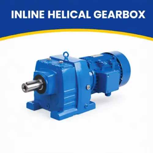
| Inline helical gearbox | Efficient, quiet, compact along one axis | Motor and output shaft are coaxial, with moderate-to-high continuous duty |
| Helical bevel gearbox | Efficient reduction with a 90-degree turn | The input and output shafts must meet at right angles and space is limited |
| Parallel shaft gearbox | High torque density and short radial height | Shafts must remain parallel, or the machine needs a low-profile drive |
| Worm gearbox | Simple, compact, quiet and economical at high ratios | Low-speed operation, intermittent duty or a right-angle layout matters more than maximum efficiency |
| Planetary gearbox | High torque density, stiffness and load sharing | Space is tight, peak torque is high, or precise, low-backlash transmission justifies the cost |
A worm gearbox deserves a thermal check, not just a torque check. Sliding contact creates more heat than comparable helical or bevel-helical gearing, especially at high ratios, low output speed and continuous duty; confirm efficiency, oil temperature, ambient temperature, mounting position and cooling together.
Do not call a worm gearbox self-locking because its ratio is high. Lead angle, friction, lubrication, wear, temperature, vibration and load direction control reverse motion; use a brake or independently validated holding device where uncontrolled descent is hazardous.
Verify the motor interface, shaft loads, mounting and operating environment
A gearbox can have enough torque and still fail because its pilot, shaft, mounting holes or bearings do not suit the machine. Confirm the complete mechanical interface before approving the quotation:
- Motor interface: match the IEC frame or NEMA frame, motor shaft diameter and length, key size, pilot register and bolt circle. For an adapter, verify the flange mounting dimensions rather than assuming a standard motor will fit.
- Output connection: specify shaft diameter, keyway, hollow-bore dimensions, coupling clearance and the position of any pulley, sprocket or gear.
- Mounting: check the gearbox footprint, bolt access and reaction-arm clearance for foot mounting or flange mounting. State whether the unit sits horizontally, vertically shaft-up or vertically shaft-down.
- Lubrication and environment: obtain the permitted mounting position, oil grade, fill level, breather location and drain access. Confirm that the seal arrangement, enclosure rating, coating and cleaning-chemical resistance suit dust, washdown, corrosive vapour or outdoor exposure.
Then compare the manufacturer’s permissible radial and axial loads at your actual load application point. A pulley or sprocket placed farther from the bearing increases overhung load; belt pretension can exceed the rating even at modest transmitted power.
Direct coupling removes that radial load but requires a correctly selected coupling to control misalignment and torsional shock.
For high-inertia equipment, reflect load inertia to the motor using Jload divided by i², but size the gearbox for acceleration, braking and reversing torque at the output. OPTIGEAR can use the drawing and load-point dimensions to check fitment rather than relying on motor power alone.
Related products
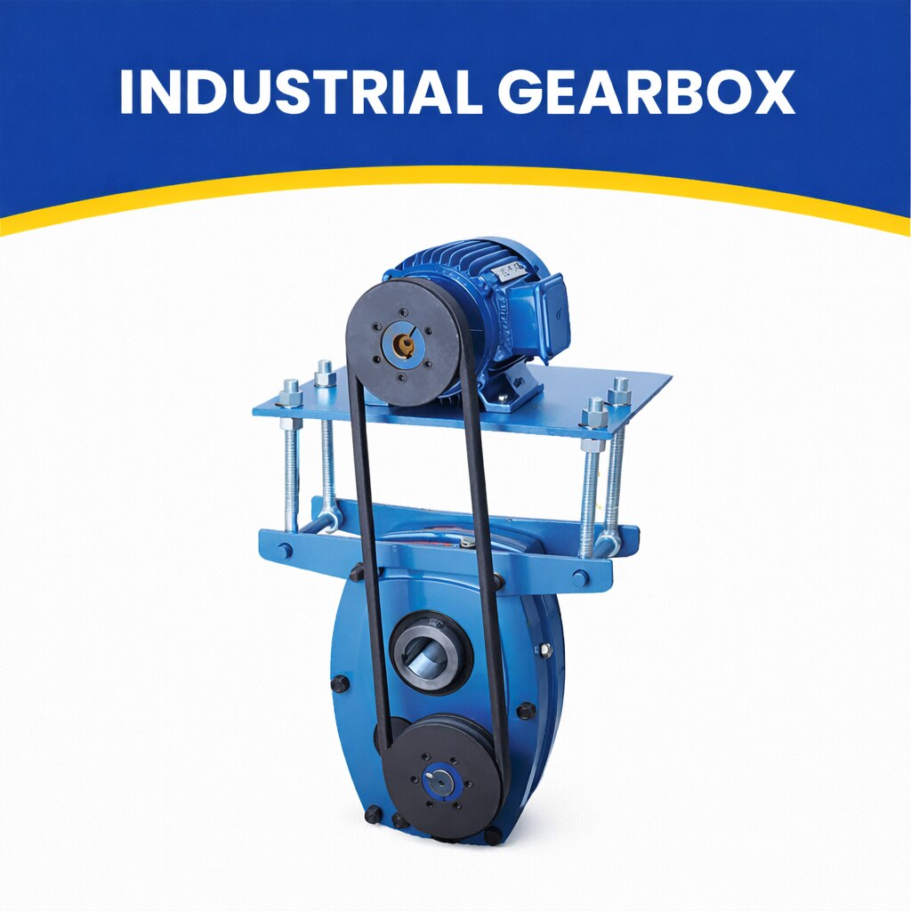 | By JRB Engineering Works JRB Engineering Works is a trusted manufacturer and supplier of high-performance Industrial Gearboxes, engineered to deliver... View product → |
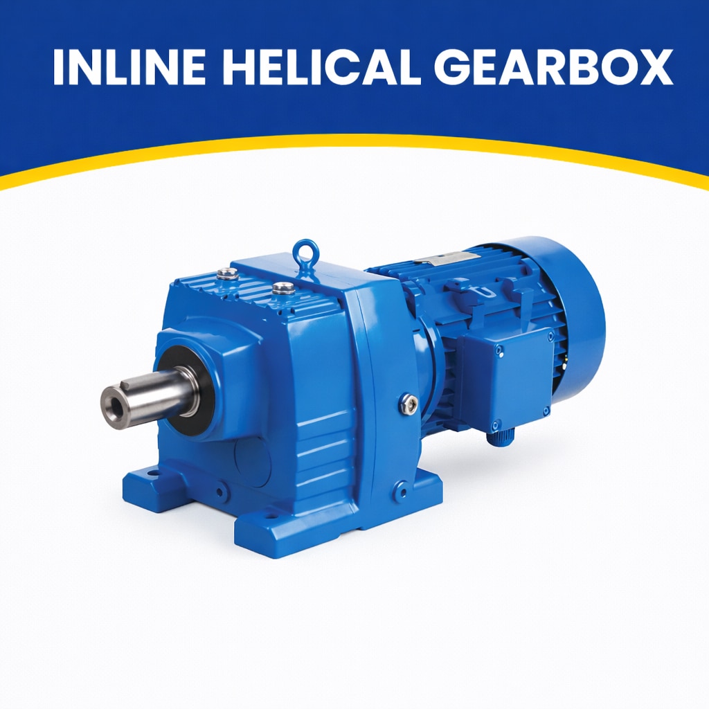 | Efficient & Compact Drive Solutions by JRB Engineering Works JRB Engineering Works manufactures high-quality Inline Helical Gearboxes designed for... View product → |
Read the rating sheet critically before approving the quotation
Approve a gearbox only after its rating sheet shows usable torque under your actual speed, duty cycle, mounting position and ambient temperature—not just nominal torque.
1. Ask the supplier to state continuous mechanical torque, peak or transient torque and thermal torque separately. Use the lowest applicable limit. A gearbox can survive a brief mechanical overload yet overheat during repeated starts or continuous operation.
2. Check how the gear rating was calculated. ISO 6336 separates tooth-root bending strength from flank-surface durability, so a passing gear calculation does not confirm bearing life, shaft deflection or overhung-load capacity. Request the load cases, service factor and assumed duty cycle behind each figure.
3. Treat ISO 281 bearing life as a calculation, not a guarantee. L10 means 90% survival under the specified conditions; contamination, poor lubrication, misalignment, electrical current and shock loading can shorten field life. Ask for the bearing loads, speed, lubricant and calculated life at your operating point.
4. Test precision and environmental claims against stated conditions. Compare backlash and torsional stiffness under load, because no-load backlash ignores elastic wind-up, coupling compliance and bearing clearance. For washdown, dust or outdoor service, verify the complete assembly’s IP rating, seal arrangement, breather, drain, coating and cleaning-chemical compatibility.
A “sealed gearbox” label is not evidence of service life.
Frequently asked questions
What machine data do you need before selecting a gearbox?
Collect motor speed and power, required output speed, duty cycle, starts and stops, reversing, acceleration, load characteristics and operating conditions. Calculate the reduction ratio from input and required output speed.
How do you size a gearbox for output torque?
Compare required output torque with the gearbox’s continuous torque, peak or intermittent torque and thermal rating. Include starting, braking, shock and acceleration loads rather than sizing from motor power alone.
Which gearbox arrangement should you choose?
Choose the arrangement by comparing efficiency, available space, output shaft orientation, mounting position, load behaviour and service requirements. Helical, bevel-helical, worm and planetary designs suit different constraints.
What must you verify at the motor and machine interface?
Confirm motor frame and flange dimensions, shaft diameter and length, coupling or hollow-shaft requirements, allowable radial and axial shaft loads, mounting details, lubrication, protection and ambient conditions.
What should you check on a gearbox rating sheet?
Check rated ratio, output speed, continuous and peak torque, service factor, thermal capacity, efficiency, allowable shaft loads, motor compatibility, mounting position, lubricant, duty cycle and environmental protection.
Related products
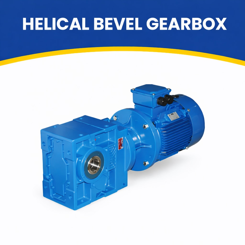 | High-Efficiency Right-Angle Drive Solutions by JRB Engineering Works JRB Engineering Works offers high-performance Helical Bevel Gearboxes designed... View product → |
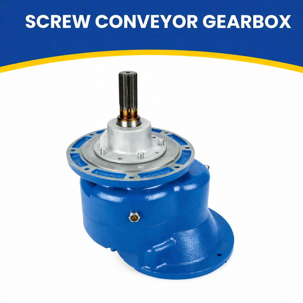 | By JRB Engineering Works Optigears is the world’s top manufacturer of screw conveyors and feeders. View product → |
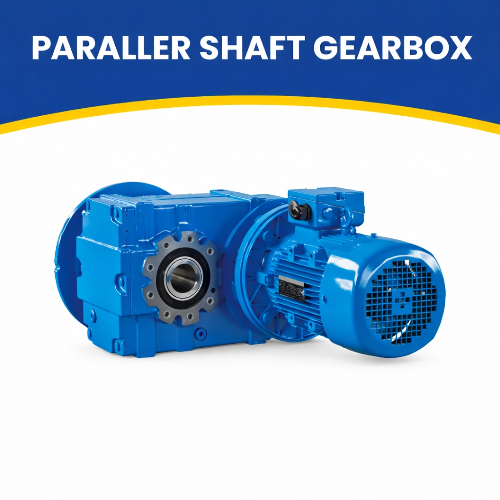 | High-Performance Power Transmission by JRB Engineering Works JRB Engineering Works manufactures and supplies Parallel Shaft Gearboxes designed for... View product → |
 | Manufactured & Supplied by JRB Engineering Works JRB Engineering Works is a trusted name in the manufacturing and supply of high-quality Kalsi... View product → |