A gearbox that matches the motor nameplate can still fail when a screw starts full, lifts dense material, runs slowly on a variable-frequency drive, or carries an external sprocket load. By the end, you will be able to calculate the required torque, compare gearbox ratings, verify mechanical fit, and prepare a supplier-ready specification.
Key takeaways
- Calculate screw-shaft torque from load, speed, diameter, and incline.
- Increase the gearbox duty rating for abrasive, hot, wet, or shock loads.
- Check shaft geometry, mounting, service factor, and brake clearance before ordering.
- Request drawings, torque data, lubricant details, and test certificates from the supplier.
What operating data determines the required gearbox torque?
Turn conveyor conditions into a defensible gearbox size by calculating required screw-shaft torque, not by matching motor horsepower alone. Good screw conveyor gearbox selection starts with these inputs:
1. Record capacity in tonnes per hour, screw diameter, pitch, filling ratio, screw speed in rpm, material bulk density in kg/m³, conveyor length, incline angle, duty hours, starts per hour, and whether each start is empty, partially loaded, or full.
2. Calculate absorbed power from conveying resistance, then add the power required to elevate material through the inclined height. Horizontal conveying power alone can undersize the drive.
3. Convert running power to shaft torque using T = 9,550 × P/n, where T is N·m, P is kW, and n is rpm. Select a reducer whose rated output torque covers running torque multiplied by the stated application service factor.
4. Calculate startup torque separately for a loaded or compacted trough. A drive sized only for steady running can stall or suffer shock damage during acceleration.
5. Check gearbox peak torque against startup and plugging loads, then verify shaft strength, coupling capacity, screw-shaft strength, and any torque limiter. Check axial conveying thrust and sprocket or chain overhung load separately; do not assume either is included in the torque rating.
How do material and duty conditions change the gearbox requirement?
Material and duty conditions determine the gearbox rating, not motor power alone. Record bulk density, particle size, abrasiveness, moisture, temperature, stickiness, corrosiveness, and the risk of bridging, packing, or tramp material.
A dense or compacted load increases starting torque. A plug can create a brief shock load far above running torque, so specify a shear pin or torque limiter set below the weakest component: screw shaft, coupling, gearbox shaft, or flight.
| Duty condition | Gearbox requirement | Failure if ignored |
|---|---|---|
| Steady continuous running | Normal application service factor and thermal rating | Overrating cost without solving a real duty problem |
| Frequent starts and stops | Higher application service factor and separate starting-torque check | Repeated acceleration damages gears, shafts, or bearings |
| Reverse operation or runback hazard | Check backdriving; add a backstop or electrically released brake | The conveyor reverses after shutdown |
| Variable-frequency-drive operation | Verify minimum, normal, and maximum speed | Low speed reduces motor-fan cooling and can exceed the gearbox thermal limit |
Check mechanical torque against thermal capacity, especially with worm reducers. Their efficiency can fall at high ratios and low speeds, so thermal capacity may govern even when mechanical torque appears adequate.
State the actual ambient temperature range, dust, washdown, altitude, outdoor exposure, motor supply, and corrosion protection. A city name is not a thermal or enclosure specification.
Which gearbox specifications and arrangement will physically fit?
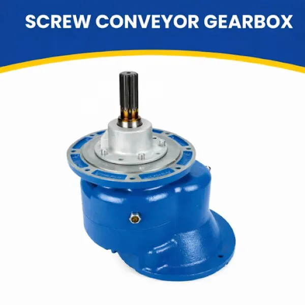
Physical fit starts with more than a motor-kilowatt match: compare screw conveyor gearbox specifications for reduction ratio, output rpm, rated and peak output torque, motor power, application service factor, thermal rating, efficiency, backlash, shaft arrangement, output-shaft diameter, keyway dimensions, mounting pattern and position, lubrication grade, seal arrangement, enclosure, motor interface, and allowable axial thrust.
| Arrangement | Clearance and alignment | Efficiency and ratio | Maintenance and thermal performance |
|---|---|---|---|
| Inline helical | Compact axial layout; precise alignment | High efficiency; moderate ratios | Easy inspection; good thermal capacity |
| Parallel-shaft | Low radial clearance; offset shafts | High efficiency; broad ratios | Accessible; good continuous-duty cooling |
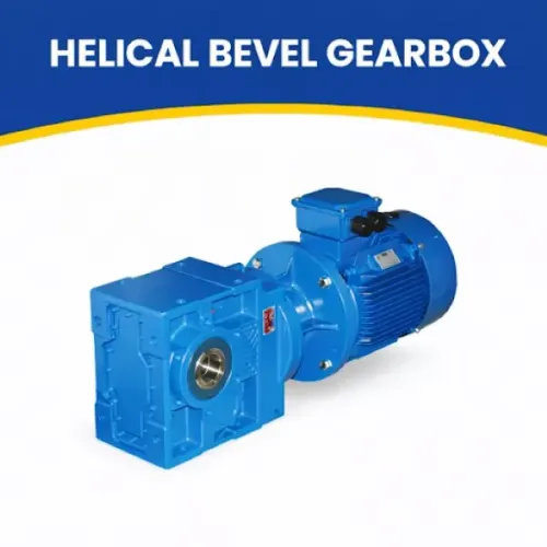
| Helical-bevel | Right-angle layout; flexible mounting | High efficiency; wide ratios | Check access; good thermal performance |
| Worm | Compact right-angle layout; alignment-tolerant | Lower efficiency; high ratios | Simple access; heat limits require a thermal check |
Check the conveyor drawing against the gearbox outline for output-shaft length and diameter, hollow-bore or solid-shaft arrangement, key and shrink-disc fit, flange or mounting feet, torque-arm location, and breather, drain, and sight-glass positions. A chain or sprocket adds radial load at a distance from the gearbox shoulder; use the catalogue’s position-specific allowable overhung-load value.
Confirm conveyor-duty rating, not only nominal motor-power sizing.
What technical documents prove that the proposed gearbox is suitable?
An auditable quotation must identify the selected gearbox and show that its ratings match the conveyor loads, not merely match the motor size.
1. Request the exact gearbox model, ratio, input and output speed, rated and peak torque, application service factor and its basis, thermal rating or calculation, permissible axial thrust, and permissible overhung load at the actual load position.
2. Obtain the manufacturer’s catalogue rating tables, mounting code, outline dimensions, shaft drawing, output shaft diameter, keyway, motor interface, lubricant specification, seal type, corrosion protection, warranty exclusions, and spare-seal availability. These documents expose fit, heat, sealing, and maintenance gaps hidden by a “5 hp gearbox” description.
3. Verify output rotation against the screw-flight direction, and confirm whether a backstop or brake is included. Check that the drive-end thrust-bearing arrangement carries the calculated screw thrust; accept reducer axial-load capacity only when the catalogue states it for that mounting and shaft arrangement.
4. Specify a torque limiter or shear device when plugging or tramp material is credible. Set it below the weakest shaft, coupling, flight, or gearbox component.
Reject any offer listing only ratio, motor kW, and price. Consider another drive architecture for extreme positioning accuracy, shock loads above the reducer rating, severe washdown, or inaccessible gearbox maintenance.
How should you install, commission, and maintain the drive?
Prevent gearbox failures by treating installation as a dimensional and lubrication check, not a motor-fitting exercise.
1. Fix the gearbox and conveyor on a rigid base, then align their shafts within the coupling manufacturer’s limits. Verify that the key fully engages both shaft and hub, with no rocking or forced fit. Install the torque arm without preload, and use the manufacturer’s mounting code.
2. Fit the specified orientation so the breather, drain, sight glass, and seals occupy their intended positions. Fill to the stated oil level with the named lubricant. Leave enough access to inspect oil and remove the drain plug without dismantling the conveyor or major guards.
3. Install guards over couplings, chains, and sprockets before energising the drive. Run unloaded and confirm rotation, noise, vibration, seal condition, and motor current; then increase the load in stages while recording gearbox temperature and motor current.
4. During service, inspect oil level and condition, seals, bearings, fasteners, shaft wear, and vibration. Rising temperature indicates overload, low oil, incorrect lubricant, poor ventilation, or low-speed thermal stress. Bearing noise indicates damage or misalignment; leakage points to worn seals, shaft damage, excess pressure, or incorrect mounting.
For output-shaft wear or recurring vibration, check hub fit, alignment, overhung load, and plugging events.
What should a New Delhi buyer send to a gearbox supplier?
Send a one-page data sheet, not a motor rating alone. Include capacity, material properties, bulk density, screw diameter and pitch, speed range, incline, conveyor length, duty cycle, starts per hour, startup load, required rotation, motor supply, VFD details, thrust, sprocket or coupling loads, ambient heat, dust, washdown, corrosion, installation altitude, and delivery location.
Ask every supplier of a screw conveyor gearbox for requirements in New Delhi to return:
- Selected model, ratio, output speed, calculations, catalogue rating tables, service-factor basis, thermal check, permissible thrust and overhung-load values.
- Outline and shaft drawings, keyway and mounting details, lubricant, seal arrangement, brake or backstop, inspection or test records, warranty exclusions, delivery scope, commissioning support, and spare-parts or service coverage.
Compare local offers on evidence, not proximity.
| Supplier evidence | What to verify | Why it matters |
|---|---|---|
| Marked-up drawings | Dimensions, shaft fit, rotation and mounting | Prevents physical incompatibility |
| Configuration options | Ratio, shaft arrangement, brake, backstop and limiter | Matches the actual conveyor |
| Testing and support | Test records and named after-sales contacts | Exposes weak commissioning coverage |
A power transmission equipment manufacturer in New Delhi earns consideration through these documents. OPTIGEAR belongs in the comparison only after supplying them. For a 15 kW, 60 rpm screw shaft, T = 9,550 × 15/60 = 2,387.5 N·m; apply the stated service factor, then verify startup torque, thrust, overhung load, rotation and fit.
Related product
 | By JRB Engineering Works Optigears is the world’s top manufacturer of screw conveyors and feeders. View product → |
Frequently asked questions
What operating data determines the required screw conveyor gearbox torque?
Use screw diameter, shaft speed, conveyor length, incline, material throughput, fill level, bulk density, friction, startup condition, and required torque to size the gearbox rather than matching motor horsepower alone.
How do material and duty conditions change the gearbox requirement?
Abrasive, sticky, corrosive, hot, wet, dense, or irregular materials increase loading or reduce component life. Account for shock loads, frequent starts, reversing, stalled starts, ambient temperature, and contamination when selecting the service factor and protection.
Which gearbox specifications and arrangement will physically fit?
Confirm rated output torque, output speed, ratio, service factor, mounting position, output shaft diameter and length, hollow or solid shaft, keyway, flange or foot mounting, motor frame, rotation, dimensions, weight, and guarding clearance.
What technical documents prove that the proposed gearbox is suitable?
Request the dimensional drawing, torque and speed rating, service-factor basis, gear and bearing details, lubricant specification, motor compatibility data, materials, inspection or test records, installation instructions, and warranty terms.
How should you install, commission, and maintain the drive?
Align the conveyor and gearbox, confirm fastener torque and shaft fit, fill the specified lubricant, check rotation and guards, run without load before loading gradually, and record temperature, noise, vibration, leakage, and maintenance findings.
Keywords