A shaft-mounted reducer is selected from the conveyor’s output speed, torque, shaft interface, duty cycle and installation constraints—not from motor power alone. By the end, you will know what data to send for a quotation, how to check the mechanical interface, and when another gearbox arrangement deserves consideration.
Key takeaways
- Provide belt speed, load, duty cycle, shaft size and site conditions.
- Calculate output torque from power, speed and service factor.
- Check hollow-bore fit, keyway, shaft length and mounting clearance.
- Require drawings, materials, warranty terms and delivery details in the quotation.
What conveyor data does a manufacturer need before selecting an SMSR?
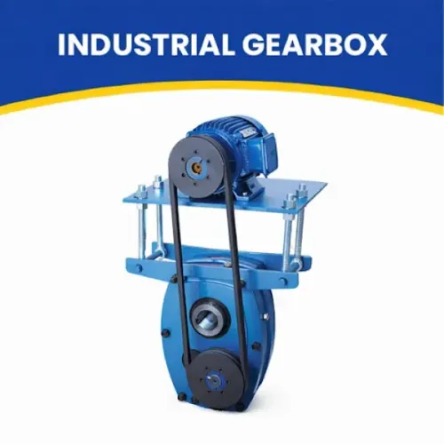
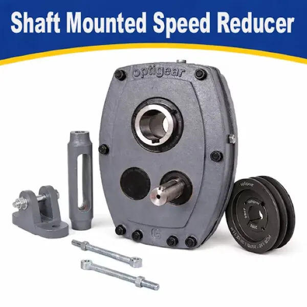
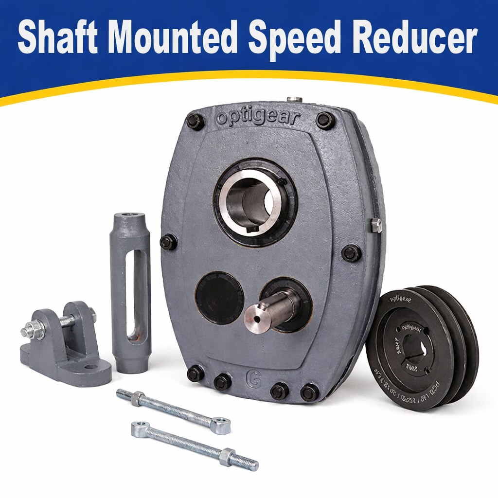
A shaft-mounted speed reducer (SMSR) fits directly onto the conveyor head-shaft or driven shaft through a hollow bore, then uses a torque arm to react gearbox force into the conveyor frame. Select it from the conveyor’s actual load and environment, not from motor kW alone.
- Conveyor type, belt width, belt speed, pulley diameter, material load and conveyor incline.
- Duty cycle, operating hours per day, starts per hour and required service life.
- Ambient temperature range, altitude, dust type, rain, monsoon exposure, washdown method, power-supply voltage and frequency.
- Site access, lifting limits and the clearance available to install or remove the reducer.
The phrase “shaft for mounted speed reducer manufacturer requirements in new delhi” combines two data sets. Shaft mounted speed reducer requirements cover gearbox selection; a separate conveyor-shaft drawing must show shaft diameter, tolerance, extension length, shoulder, material, keyway and bearing locations. Without that drawing, the manufacturer cannot confirm hollow-bore fit or shaft loading.
For Delhi, include hot ambient conditions, airborne dust and monsoon rain in the quotation. State whether water cleaning reaches the reducer. These details affect seals, breather protection, lubricant choice and thermal capacity, so a local supplier’s location alone is not a technical specification.
How do you calculate output speed, torque and reducer capacity?
Calculate output speed from belt speed and pulley diameter: n = 60v ÷ (πD), where v is belt speed in m/s, D is pulley diameter in metres, and n is output speed in r/min. Calculate reduction ratio as motor speed ÷ required output speed.
Estimate running torque with T = 9,550 × P/n N·m, using transmitted power P in kW and output speed n in r/min.
Motor kW alone is insufficient for shaft mounted speed reducer requirements. Multiply running torque by a service factor based on operating hours, starts per hour, load variation and shock, then compare the result with the reducer’s rated torque. Check these events separately against permissible peak torque:
- Motor starting and locked-rotor torque
- Jam torque
- Stalled-belt torque
- Regenerative overrun torque
A supplier must also distinguish mechanical capacity from thermal capacity. A reducer can transmit the required torque mechanically yet overheat at low speed, high ambient temperature or continuous duty.
| Rating | What it limits | Check |
|---|---|---|
| Mechanical | Gear teeth, shafts and bearings | Rated torque, peak torque and external loads |
| Thermal | Heat dissipation during operation | Output speed, ambient temperature, duty and mounting position |
For an inclined or declined conveyor, specify backstop direction and torque, stopping conditions, and internal or external arrangement. Confirm rotation before commissioning; reversing motor phases against the backstop direction can cause immediate damage.
How should you verify the conveyor shaft, hollow bore and mounting space?
Verify the conveyor shaft before ordering: a hollow-bore reducer is not interchangeable with every driven shaft. Give the shaft mounted speed reducer manufacturer a separate shaft drawing, not only a gearbox torque figure.
Measure and record:
- Driven-shaft diameter and tolerance
- Shaft extension length and shoulder position
- Keyway width, depth, key length and key size
- Bearing locations and shaft runout
- Available reducer-removal clearance
- Shaft material and any stepped or threaded sections
The drawing must show the diameter, tolerance, keyway, shoulder, bearing positions and material so the manufacturer can check fit and strength.
| Connection | Compare against the reducer | Use when |
|---|---|---|
| Keyed hub | Bore, keyway width and depth, key length, and shaft extension | The shaft and hub share a specified clearance or interference fit |
| Taper bush | Bush bore, taper, key and clamping length | Shaft dimensions need a replaceable bush or adjustment |
| Shrink disc | Clamping diameter, shaft length, surface condition and installation clearance | High torque requires friction clamping without a key |
Specify a bush when the standard bore does not match; use an adapter or custom shaft arrangement when the extension, shoulder or key cannot meet the hub drawing. Submit radial, axial and overhung load magnitude, direction, application point and speed.
The conveyor shaft must withstand reducer reaction plus loads from the pulley, sprocket, chain or belt; torque-only selection can overload bearings or the hollow-bore connection.
How do torque-arm design and mounting position protect the drive?
The torque arm carries gearbox reaction torque to the conveyor frame while allowing limited relative movement between reducer and frame. Anchor it at the specified rigid frame point, in the reaction-load direction, and keep its permitted movement free from belt, pulley and guard interference. Fit the specified flexible bushings; do not let the arm bind.
Rigidly bolting the reducer, positioning the arm incorrectly, or omitting flexible bushes transfers reaction and bending loads into gearbox and conveyor bearings. The result can be bearing failure, seal leakage, shaft deflection and a cracked mounting structure. These are shaft mounted speed reducer requirements, not optional installation preferences.
Check the installation for:
- Conveyor-shaft runout and hollow-bore or hub fit
- Angular error between reducer and conveyor shaft
- Soft foot at the reducer or support
- Pulley imbalance and shaft deflection
State the exact orientation: horizontal or vertical shaft, torque-arm side, oil level, breather position and lubricant. Orientation changes bearing lubrication and thermal rating, so use the manufacturer’s specified fill and breather arrangement.
Treat dusty service separately from motor IP rating. Specify seals, protected or remote breather arrangement, enclosure exposure to dust, rain and washdown, and the cleaning method; compressed air can drive abrasive dust past seals.
When is an SMSR preferable to another gearbox arrangement?
An SMSR is preferable when the conveyor head shaft accepts its hollow bore, the reducer can slide into position, and a torque arm has a safe reaction path. Direct shaft mounting removes a separate coupling and baseplate, reducing alignment work, footprint and installation labour.
| Arrangement | Driven-shaft access | Efficiency and footprint | Maintenance, removal and cost |
|---|---|---|---|
| SMSR | Direct hollow-bore fit | Efficient, compact; no coupling alignment | Needs axial withdrawal clearance; often lower installation cost |
| Inline helical | Coupling required | Efficient, but needs base space and coupling alignment | Easier access in some layouts; coupling and baseplate add work |
| Parallel-shaft | Coupling or specified shaft arrangement | Compact across the conveyor width; efficient | Good for restricted radial space; removal depends on base and coupling access |
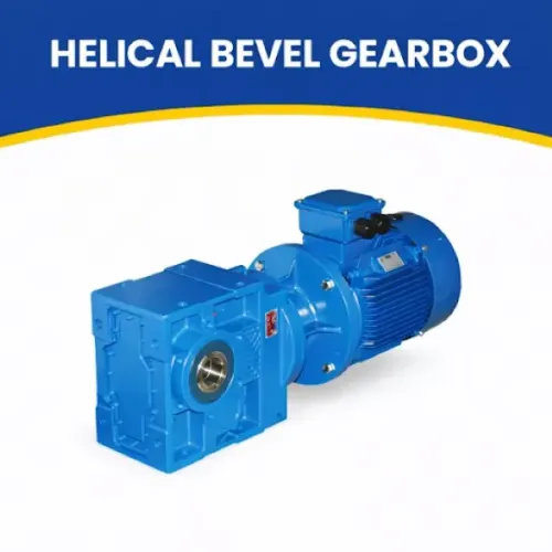
| Helical-bevel | Usually coupling or flange interface | Changes drive direction; efficient, but layout-dependent | Useful for right-angle routing; extra interface work affects cost |
Use this engineering check before choosing the product name:
1. Confirm shaft diameter, tolerance, key or shrink-disc connection, extension length, bearing support and reducer-removal clearance. A hollow bore does not make SMSRs interchangeable.
2. Check runout, angular error, soft foot, pulley imbalance and shaft deflection. These faults create cyclic loads and seal failures.
3. Verify the torque arm’s anchor, flexible bushes, clearance and force path. Reject the arrangement if severe shock, frequent reversing, inadequate support or restricted service access remains.
4. For inclined or declined conveyors, specify backstop type, torque, rotation and rollback conditions. Confirm rotation before commissioning; reversing phases against an internal backstop can destroy it. A shaft mounted speed reducer manufacturer should validate every item.
What should a Delhi supplier include in the final quotation?
A final quotation should convert the selection into a purchase specification, not merely name a gearbox model. Require these items:
- Dimensional drawing, hollow-bore diameter, keyway width, depth and length, and shaft-interface details
- Rated torque, peak torque, service factor, mechanical rating and thermal rating
- Allowable overhung and axial loads, with load direction and application point
- Mounting orientation, torque-arm position and backstop direction and torque
- Motor interface, supply voltage and frequency
- Lubricant grade and viscosity, initial fill, oil-change interval and synthetic-oil compatibility
- Ambient-temperature range, dust and monsoon exposure, noise or vibration limits
- Factory test documents, spare-seal availability and spare-bearing availability
- Belt speed, pulley diameter, inclination, material load, starts per hour and duty hours
- A shaft drawing showing diameter, tolerance, keyway, shoulder, extension, material and bearing locations
“Shaft mounted speed reducer supplier in delhi” describes location, not technical suitability. OPTIGEAR is relevant when your supplier discussion must address these conveyor and shaft-interface fields rather than a nominal gearbox match.
Related product
 | Manufactured & Supplied by JRB Engineering Works JRB Engineering Works is a trusted manufacturer and supplier of high-performance Shaft Mounted Speed... View product → |
Frequently asked questions
What conveyor data does a manufacturer need before selecting an SMSR?
Provide belt speed, conveyor capacity, belt width, drive-shaft speed, load, duty cycle, starts per hour, incline, ambient conditions and installation orientation.
How do you calculate output speed, torque and reducer capacity?
Calculate output speed by dividing motor speed by the total reduction ratio. Calculate torque from power and speed, then apply the manufacturer’s service factor for starting, shock and duty conditions.
How should you verify the conveyor shaft, hollow bore and mounting space?
Match the reducer bore to the shaft diameter and keyway, then confirm shaft length, shoulder location, bearing loads, access for installation and clearance around the housing.
How do torque-arm design and mounting position protect the drive?
Use a correctly aligned torque arm attached to a rigid frame point with suitable flexibility. Keep the arm from carrying belt pull or misalignment loads into the reducer.
When is an SMSR preferable to another gearbox arrangement?
Choose an SMSR when compact shaft-mounted installation, fewer couplings and straightforward conveyor access matter. Use another arrangement when shaft loads, space or alignment conditions exceed SMSR limits.
Keywords